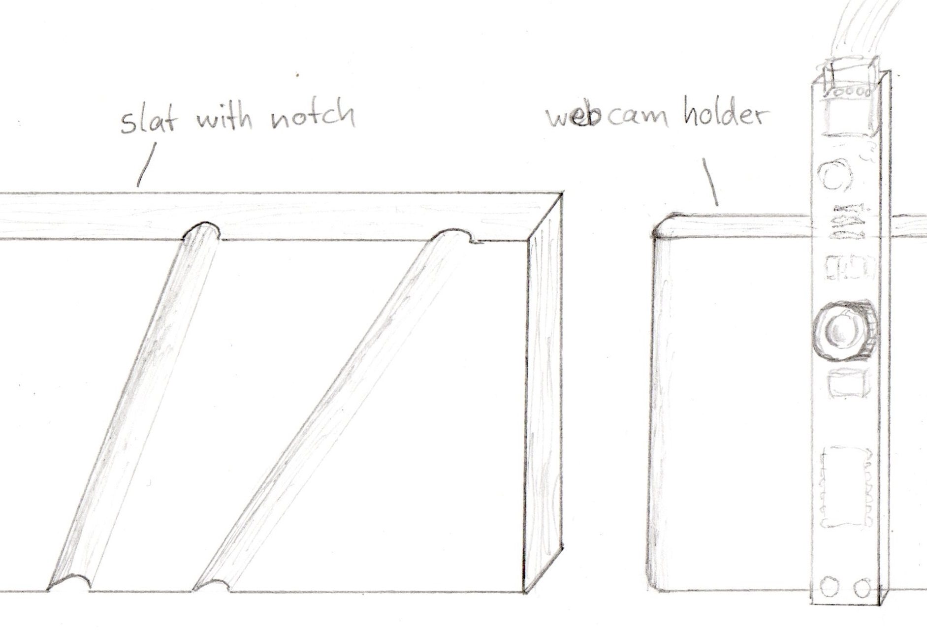
I read a lot about a more rigid setup of the PLab spectrometer in this forum. So I thought about how to avoid the velcro- and paper instabilities and came up with this idea:

The webcam and grating foil holder would slide into the notches and keep the angles stable. You could build this from would or - as Warren proposed - laser-cut it from acrylic, which would cost more but be more moisture resistant. As for the DVD grating, I would exchange this against a ready made 1000 lines/mm diffraction grating slide that you get for instance at amazon for just $ 2.32. You could also use a 500 lines/mm or even 13500 lines/mm slide if you want. Somebody should be able to calculate which is best.
You can glue the side walls to the base block and add another notch slide for the slit in front of the spectrometer.
Oh, and has anyone thought about what happens if you dim the incoming light with two rotatable polar filters? Might prevent the webcam from over-exposure but I'm not sure if it changes the curves somehow. Could be worth a try.
And I still think it would be great if we could switch off the gain control of the webcam, too.
17 Comments
Sorry about the typo. I meant "You could build this from wood or ..."
Reply to this comment...
Log in to comment
Awesome! I did some sketches for a multiple piece outside enclosure that could be prototyped in cardboard but final cuts in laser cut acrylic:
Long bolts would go across and hold it together, and it could enclose the existing spectrometer design (this has benefits for being more consistent with existing data, and being essentially an add on for the existing manufactured design, so people could upgrade). The internal stability is another question your and @stoft's designs might get at. @tonyc and I had chatted a bit about this but you're moving faster than we are! Thanks!
Reply to this comment...
Log in to comment
Hmmm... a few counter thoughts.
1) To match the camera optics with the grating to keep the spectral band spread across the pixels seems to require (this is what I've found best) the grating to sit flush with the camera -- the parallel grating and camera thus mounted at 45-deg to the optical path to the slit. 2) This also helps the design as the slit is then in-line with the 45-deg grating / camera module, which is thus inline over the longer dimension of the spectrometer. 3) I frequently have laser-cut acrylics made, in lots of several hundred, and the simplest ones are still about $3.50 each -- the process is not cheap. Keep the thought-experiments open ...... 4) The internals ARE still the problem as that is what provides the optical path stability -- much more than the cover. So, I see Jeff's perspective as reversed. The cover could be paper (perhaps....) but the internals are the critical part. 5) The slit needs to be replaceable but, when mounted, very stable. 6) The slit to grating / camera distance is where the flexure is greatest. 7) First, mount the grating to the camera as in integral sub-assembly. This keeps that optical relationship stable. This is a necessity because we are talking angstroms, pixels and nm. 7a) I tried using the holographic diffraction gratings mounted on 35mm slide frames. The finer line width was not helpful with the 640x480 camera and the film is much too flexible. The DVD may not be very sexy, but it's rigid construction is an inherent advantage -- and the line density is more than enough. 8) Then, mount that sub-assembly (rigid, like glue it) to a bottom base-plate frame which is thicker to maintain it's stiffness when supporting the slit. 9) Mount the slit-holder to the other end of the base-plate (i.e. glue it). The result should not show flexure which would alter the optical path. 10) Add a mechanical de-coupling loop in the USB cable (between camera and where it exits the housing) and strain-relief the cable to the base-plate (not the housing!) before exit. 11) After all of this, then provide a light-tight covering. In my proto, I used a sheet of black paper, bent in a U-channel. 12) Finally, all of that could be placed in a user-friendly "shell" with Logo -- though still, the internal base-plate needs to be 'attached' mechanically to the 'base' of the shell because the shell is what the user will handle or mount.
Hope this adds some clarity.
Reply to this comment...
Log in to comment
Hi Chris,
do you mean "sit flush" as in "parallel", "pressing tightly against it"? I thought you had a good reason for the 20° angle between DVD and camera?
Is this a question? Click here to post it to the Questions page.
Reply to this comment...
Log in to comment
PS: I guess if you use acrylic you need a real dull black finish to prevent stray light.
PPS: when I thought about a new setup I also came to a "Captain Nemo"-like solution made from brass with a hundred little adjustment wheels for angles, distances, slit opening and so on but I guess that wouldn't meet budget requirements, would it? ;-)
Is this a question? Click here to post it to the Questions page.
Reply to this comment...
Log in to comment
I believe the configuration with 45 and 20 deg was extracted from physically experimenting on the first PLab design. ( I think they were having difficulty mounting the grating close to the camera with Velcro...). I included the following ray-trace in one of my notes which looked at image non-linearity:
The spacing from grating to camera is essentially decided by the camera lens so ends up being very close and parallel; but not touching -- which puts the camera sub-assembly at 45-deg to the normal from the slit. Fortunately, this makes the camera / grating module simpler.
Reply to this comment...
Log in to comment
So... how about turning the (DVD holding) paper thing around and create a paper housing all around the wooden block with a parallel surface, a rectangle hole and have the DVD glued to it? This way you get a more rigid but similarily cheap sub-assembly that doesn't depend too much on the velcro. You could even glue the wooden block to the wooden base. You could also print a line onto the wooden base saying "glue the wooden block exactly here!"
Is this a question? Click here to post it to the Questions page.
Reply to this comment...
Log in to comment
You mean something like this? (from https://publiclab.org/notes/stoft/03-02-2015/plab-3-spectrometer-upgrade-prototype):
Yes, mine could be simplified some by cutting a u-channel shape, just slightly deeper than the thickness of the camera, and then cutting sections at 45-deg.
Is this a question? Click here to post it to the Questions page.
Reply to this comment...
Log in to comment
Thanks, Dave - actually, that sounds reasonably cheap vs. quotes we get for wood manufacturing, but I wonder if you'd be willing to share where you get acrylic cut, and/or if you know of places that do affordable wood manufacturing?
I've been starting to think of a possible design in three parts:
I think the rigid interior could be built inside the existing device, and a pretty affordable exterior enclosure could fit outside. Obviously we could simplify the paper if it's just light-blocking, but I'd like to keep thinking about how new designs could be upgraded-to by folks who have the current kit. Not a hard constraint, but unless there's a solid reason to abandon that as a constraint, it's nice to have.
So, I was thinking -- could we post a "spec for the spec" as a kind of challenge -- using the steps Dave outlined in the comments on his post a couple days ago. That is, whatever designs people post (and/or collaborate on) would have to be run through a simple test, and to meet these specific empirical specs, to "pass" as a design. Another constraint could of course be cost, though we can pool resources/knowledge on manufacturing processes and vendors to keep that low.
If you're interested, it'd be nice if @stoft could post it, since he enumerated the "first draft" of the specs. We could iterate on the specs as well, of course, and I'm happy to post it as well. I think it'd need a clear "testing methodology" that people could follow, and a numbered set of "specs" it'd have to meet. Thoughts?
Is this a question? Click here to post it to the Questions page.
Reply to this comment...
Log in to comment
The little thing with the hole in front of your DVD - is this for preventing stray light coming in?
Is this a question? Click here to post it to the Questions page.
Reply to this comment...
Log in to comment
@viechdokter, yes, it was just an experimental baffle for stray light. Keeping reflections low inside the space between slit and grating is necessary as the slit can let in light from any angle. While the only light we care about is that which is inline with the grating, that doesn't mean that will be the only light traveling inside the enclosure. But, no, the baffle doesn't require rigid mounting in the way that the camera does -- using the same style mounting parts was simple the easiest thing to do and the rigid mount doesn't hurt.
Reply to this comment...
Log in to comment
Also see some of the suggestions here, which experiment with interior rigidity as well: https://publiclab.org/notes/ygzstc/08-19-2015/some-suggestions-for-spectrometer-v3-0-and-oil-testing-kit-otk-attachment
Reply to this comment...
Log in to comment
Jeff, I have a local supplier call Tap Plastics but I assume laser-cut plastics are now available in most metropolitan areas.
Ok, that's fine to keep the previous version in mind. In fact, my basic proto spectrometer module does fit that paper housing. I just abandoned it when I discovered there are simpler ways to cover and there remained the issue that that paper housing decoupled the base optics from the user's mounting -- i.e. the user can hold / mount the paper but that doesn't actually control the mechanics of the base optics. That ends up adding mechanical motion to the optics which is only indirectly related to the housing. Sorry, but there is just no substitute for rigid mounting -- either it is or it is not.
Yes, the idea of a measurement reference test is a good one. Actually, I'd previously suggested that a CFL signature might form such a reference. While I'm not finished decoding the SWB 'quality' rating code and implementing some comparative testing, I don't think that value is the correct one. I think a check of several specific factors of a CFL signature might provide better analysis of spectrometer performance -- like how well the double-green peak is resolved. That said, I'd still suggest that work on both such a qualification test and work on a replacement product design continue together. Many design concepts can be analyzed just through thought experiments w/o building hardware or involved testing. In parallel, if users are to be able to test and qualify their spectrometers, than those algorithms need to be implemented in whatever software is commonly available -- SWB for now it seems.
I'd suggest 3 things are required: 1) a list of what is to be tested and the basis of the criteria for passing the tests, 2) three lists of specifications, a) the measured (so far) spec limits under the best of conditions and b) the specs that we'd expect a product to pass in the hands of the user and c) a slightly tighter manufacturing spec (i.e. a 'professionally built kit will pass'), and 3) a set of specs the mechanical design must meet and the reasons those specs were selected (eg, materials cost, assembly tools, rigidity, light-tight qualities, assembly compatibility, legacy options, modularity (i.e. adaptability for an OTK, etc.). Should also keep in mind that some might be willing to pay extra to get a fully assembled version.
Might need 3 dedicated spaces for these topics to evolve.
Reply to this comment...
Log in to comment
Warren,
I know that the spectrometer that I have built is extremely rigid, but it is not made of cardboard, It is made from square black plastic rainwater down-pipe. If you look back through some of my submissions you will see photos of it. Is black plastic rainwater down-pipe available in the USA? If it is, I will gladly describe how I made my rigid and opaque spectrometer.
Guillaume851
Is this a question? Click here to post it to the Questions page.
Reply to this comment...
Log in to comment
Thanks, Guillaume851 - I've seen yours and it does look very rigid, thank you! Part of the design I'm prototyping in my note here is a design we could lasercut from acrylic and sell with our current kit, and that is easy to make from materials available everywhere in the world, even without a lasercutter.
Reply to this comment...
Log in to comment
Hi, everybody!!! We've finally developed a new approach to posting/sharing/collaborating, and are looking at how this extends into hardware modifications as well.
You can read a bit about the Questions system and the Activities system on these posts: #activity-grids
But, following up on this series of ideas, a few questions and one "Upgrade" have been posted which I hope will help us to take steps forward:
https://publiclab.org/notes/stoft/09-16-2016/stability-upgrade-mockup-for-plab-spectrometer-3-0 (which riffs on ideas here and in other notes)
And one "replication" or "build" of that documented upgrade: https://publiclab.org/notes/warren/09-20-2016/building-the-stoft-stability-upgrade-for-desktop-spectrometry-starter-kit-3-0
Formulating a question about light leaks/ambient light: https://publiclab.org/questions/warren/09-19-2016/how-can-i-reduce-ambient-light-inside-the-desktop-spectrometry-starter-kit -- I imagine this may lead to another "upgrade" or two, which others could replicate.
I encourage folks to:
Thanks!!!
Reply to this comment...
Log in to comment
warren awards a barnstar to viechdokter for their awesome contribution!
Reply to this comment...
Log in to comment
Login to comment.