What I want to do:
I want to develop a syringe pump that can be made by anyone with minimal tools and skills. Many routine laboratory tasks are subject to automation and syringe pumps are the necessary first component in any automated fluidics project. Examples of such tasks include routine titrations, making pH buffers. Other examples could include repetitive synthetic procedures such as solid phase synthesis of things like peptides or DNA primers. While commercial instruments are available for these types of tasks, they are currently expensive as all get out.
My attempt and results:

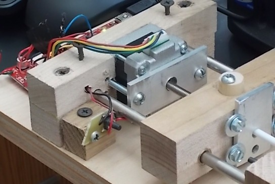
As shown in the figure, the pump was mounted on a piece of 3/4" cabinet grade birch plywood. There are blocks on the ends of the pump that hold 1/4" stainless steel rods and a central block rides on the rods. The ends and central block are made of soft maple. The motor and driver are from Sparkfun (part numbers ROB-10848, $29.95 and ROB-10267, $14.95). The thing is run off a computer using a texas instruments launchpad development board (MSP-EXP430G2, $9.99 from TI). There is no reason you can not use an Arduino if you prefer that system. The design requires the motor we list. The motor has an internal nut and a threaded shaft runs through it. The motor comes with a 100 mm shaft. This was chosen to eliminate the need to purchase a separate drive screw / nut / coupling. The 100 mm shaft is a little short and I have not found replacement stock. At the ends of travel, the center block encounters a button switch that tells the microcontroller to stop. In the next iteration I will use a different type of switch.
You will notice that this is revision 2.3 of the pump project. We tried making the pump carriage out of a variety of materials, including aluminum and white oak. The biggest hurdle here was aligning the holes for the rails. The holes need to be strictly co-linear or else the thing binds up and goes nowhere. You might think this would be fairly easy to do, but drill bits tended to wander around the surface of aluminum and to follow the grain of the oak. In the next paragraph I describe making the carriage out of wood using a drill press and a table saw. If you are thinking "I can make a better one of those with my (CNC machine / laser cutter / 3D printer)", fine, you can skip the next paragraph. The following directions are intended for someone who wants to make one of these for her kid's high school and only has access to a limited wood shop.
Step 1; cut two short and wide pieces of 3/4" maple. I started with a 4.5" board and cut the pieces to 3.5" length.
Step 2; Use the table saw to cut three shallow (1 mm deep), narrow (1 mm across), parallel grooves across the grain of one of the above bits of wood. The first should be in the center of the piece, the second and third should be about 1 3/8" on either side. To keep these groves parallel, use the rip fence to guide the wood, keeping the same face down and the same end against the fence for each cut.
Step 3: Glue the faces of the two pieces of maple together, keeping the grooved face on the inside. You now have three parallel square holes running across the width of 1.5" thick block of wood.
Step 4: Cut the block with the grain (across the groves) to give three 1" wide pieces. These will be the two ends and the center block. The square holes that were once grooves will serve as pilot holes and will keep your drill bits from wandering.
Step 5: Drill holes for the steel rails: For the center block, these holes should be 3/8" diameter to accept a 1/4" sleeve bearing (available from Grainger, part Item # 2X355, $4 for a three pack, you will need two). If you want it to be purty, you might want to polyurethane the block before pressing the bearing in (use a C-clamp to press the bearing). We purchased the stainless rod from metalsdepot.com. The item number is R414 and you can get a 2 ft section for $2.50 plus shipping.
Questions and next steps:
The next step is to get the code on GitHub. We have microcontroller and GUI code written, but ... yeah. Me and GitHub are not on bff status.
The step following that is to write code for the automated valve system. If you want to automate DNA synthesis youre going to need to switch valves on and off. I just got the valve put together this morning, but I have not even started looking at servo code.
 Let me know if you have questions.
Jack
Let me know if you have questions.
Jack
5 Comments
What about using MDF? Wouldn't that get rid of the issues with wood grain?
Is this a question? Click here to post it to the Questions page.
Reply to this comment...
Log in to comment
I have never been very happy with my results when machining mdf. It does not take fasteners well (especially screws) and I recall having trouble with gluing. Perhaps with experience I could improve my mdf technique, but it is not a priority for me. Jack
Reply to this comment...
Log in to comment
I'm glad you skipped the laser cutters etc. and went straight to the wood shop. far more accessible. My experiences with MDF are similar. It loves swelling in contact with liquid, including glue. not the best thing to have around a lab.
Reply to this comment...
Log in to comment
An arduino would be able to be used in place of both the development board and the motor driver, right?
Is this a question? Click here to post it to the Questions page.
Reply to this comment...
Log in to comment
Hi, Since this uses a stepper motor (12 volts), I think you will need the motor driver. The Arduino will do the job of the LaunchPad that we used.
Jack
Reply to this comment...
Log in to comment
Login to comment.