Purpose
This note is part of a series on setting up, testing, and calibrating the DF Robot analog liquid sensors.
Because all of the sensors in this series share a common interface, much of what you need to do to set up and use them is the same regardless of which sensor you are using.
See this guide for an overview of the sensors and the basic setup process.
This note contains details about the process that are specific to using the ph Sensor with the Arduino. The section headings in this guide all link to the corresponding sections in the general sensor overview guide.
Required Materials
- DF Robot pH Sensor ($29.50) or pH Sensor Pro ($56.90)
This is the sensor that we are going to be using to collect data. DF Robot sells two different pH sensors. The two sensors have different probes but share the same circuit board for connecting to the Arduino, so the process of setting them up and using them is the same for both.
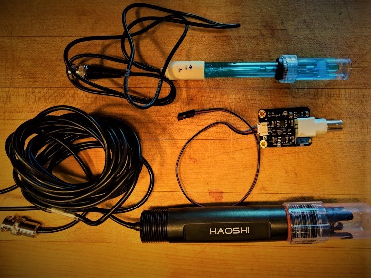
The main difference is that the more expensive "pro" sensor probe can be immersed in liquids for long periods of time so is suitable for projects that require constant monitoring whereas the standard probe cannot be used continuously.
The "pro" sensor also seems to respond to changes in pH more quickly.
- See the materials list in the series overview for other materials.
Step 1: Testing Your Arduino
Before we do any work building the circuit for our sensor or writing code for the Arduino, we want to make sure that the Arduino works on its own and that we can connect to it using our computer.
To test the Arduino, we need to install the Arduino IDE software, connect the Arduino to our computer, and upload a simple test program to verify that everything is functioning. If we do this before we do any other work then we will know that we are starting with a functioning Arduino.
For more detail see: Setting Up and Testing an Arduino.
Step 2: Connecting Your Sensor to Your Arduino
Regardless of whether you are using the standard or the pro version, the pH sensor consists of two parts, the sensor probe and the circuit board. This can be connected to each other and to your Arduino with the included sets of wires.
The circuit board looks like this:
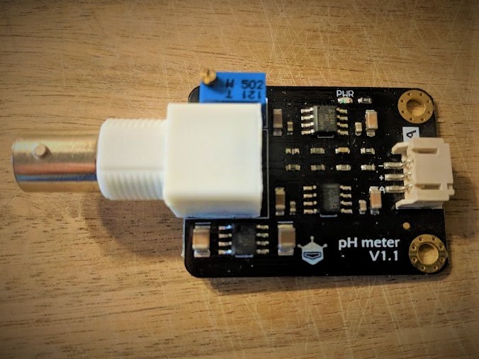
It has a large plastic barrel connector for the probe on the left-side and a small plug for a set of three wires on the right. The wires on the right will connect to the Arduino.
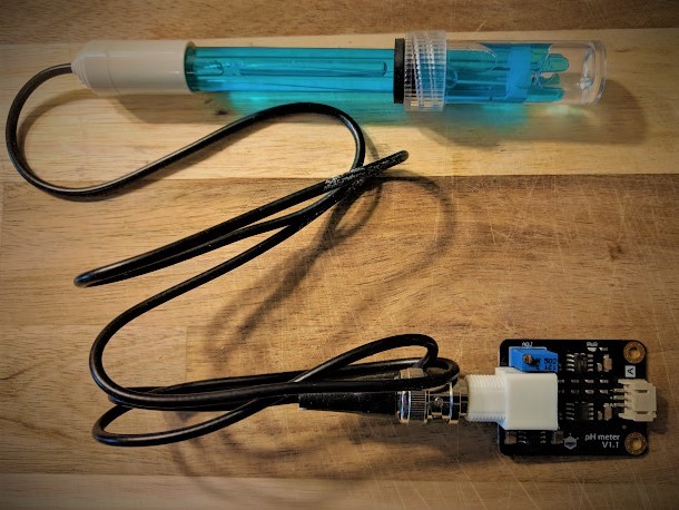
The probe can be plugged into the connector on the left:
Step 3: Connect Hook-up Wires to Sensor Circuit Board
The sensor comes with a cable with three wires -- BLUE - RED - BLACK. This cable has a white plastic plug connector on one side that plugs into the circuit board. On the other side it has a black plastic socket connector that you can plug three jumper-wires into.

Plug this cable into the plastic connector on the right-hand side of the circuit board.
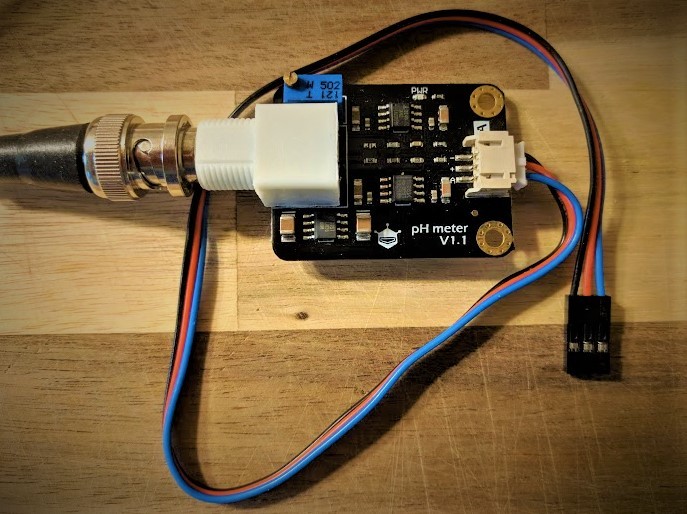
Then plug three jumper wires into the socket on the other side. I like to use jumper wires that are the same color as the cabling that I'm plugging them into so I don't get confused.
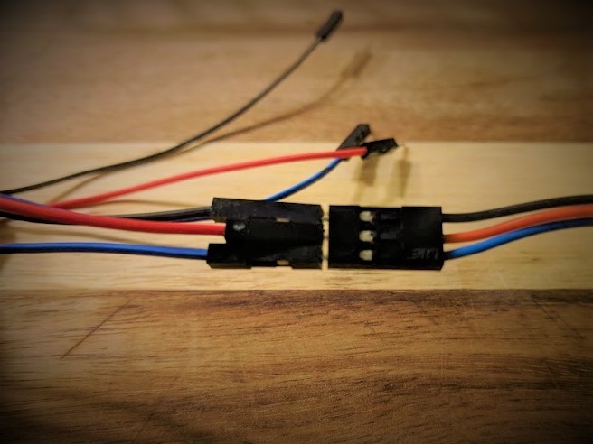
Step 4: Connect Sensor Circuit Board to Arduino
See this section in the overview guide for instructions.
The DF Robot analog sensors all share a common design so that they all connect to the Arduino in the same way.
Step 5: Upload and Test Code
For more information about the general process of finding and using Arduino code to work with sensors see this section in the overview guide.
The pH Sensor guide on the DF Robot wiki has sample code that we can use to get started.
The most important thing to note about this code is that at uses the analog pin A0 to read input from the sensor. This means that we need to make sure we plugged our sensor's DATA (BLUE) wire into pin A0.
/*
 # This sample code is used to test the pH meter V1.0.
 # Editor : YouYou
 # Ver    : 1.0
 # Product: analog pH meter
 # SKU    : SEN0161
*/
#define SensorPin A0            //pH meter Analog output to Arduino Analog Input 0
#define Offset 0.00            //deviation compensate
#define LED 13
#define samplingInterval 20
#define printInterval 800
#define ArrayLenth  40    //times of collection
int pHArray[ArrayLenth];   //Store the average value of the sensor feedback
int pHArrayIndex=0;
void setup(void)
{
  pinMode(LED,OUTPUT);
  Serial.begin(9600);
  Serial.println("pH meter experiment!");    //Test the serial monitor
}
void loop(void)
{
  static unsigned long samplingTime = millis();
  static unsigned long printTime = millis();
  static float pHValue,voltage;
  if(millis()-samplingTime > samplingInterval)
  {
      pHArray[pHArrayIndex++]=analogRead(SensorPin);
      if(pHArrayIndex==ArrayLenth)pHArrayIndex=0;
      voltage = avergearray(pHArray, ArrayLenth)*5.0/1024;
      pHValue = 3.5*voltage+Offset;
      samplingTime=millis();
  }
  if(millis() - printTime > printInterval)   //Every 800 milliseconds, print a numerical, convert the state of the LED indicator
  {
    Serial.print("Voltage:");
        Serial.print(voltage,2);
        Serial.print("    pH value: ");
    Serial.println(pHValue,2);
        digitalWrite(LED,digitalRead(LED)^1);
        printTime=millis();
  }
}
double avergearray(int* arr, int number){
  int i;
  int max,min;
  double avg;
  long amount=0;
  if(number

0 Comments
Login to comment.