Features
- Enhanced resolution and accuracy (theoretically 0,4 pixels/nm)
- Reflectance spectrometer with 2 channels (Toslink cables as light transmitter) --> allows a non-linear spectral light source
- NoIR-raspberry camera measures first spectral maximum
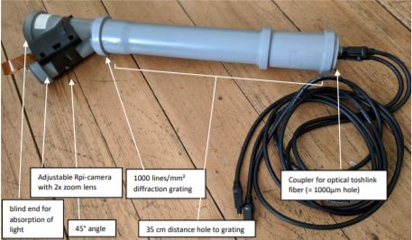
- Grid with 1000 lines/mm & no slit
- Modular design with watertubes: HT DN50 / EN 1451 B
- Costs: around 100 €
- Portable with power-bank
How it works

The main idea for using two optical cables is that one is pointed at the light source* and one measures the reflectance from the object of interest. So, by subtracting the source-spectrum minus the reflected-spectrum you should get the absorbed wavelengths. The nice thing about this method is that it should not be dependent on a linear spectral light source or on linear absorption of the camera’s sensor to gain valid spectrums.
Results

This is the spectrum of sunlight as measured. The spectrum starts at 420 nm and ends at 845 nm. At 760 nm the absorption band of the oxygen in the atmosphere is circled green. Another weird dent is marked blue; this is an absorption of the toslink cable (see next pic). I also tested two 600µm optical cables for spectrometers and they don’t show this dent (see 2nd pic below). However, two of those fibers cost around 100€ even at Alibaba.


So, I don’t want to lose myself into detail here. In general, I tested reflectance with a grey card and colour checker and the spectrometer turned out to measure different colours easily.
*Cosine Corrector: to reduce direct light and the angle of the light source’s a cosine corrector is used in normal spectrometers. When sunlight enters the fiber directly, an overexposure in the spectrum is the result (see 2nd next picture). It turned out that a table tennis ball performed pretty well when the cable was sticked into it. It should be a white and relatively transparent one. The cosine corrector is used for sunlight as the light source.
Calibration Calibration was done with a normal CFL lamp (see recorded spectrum in the next picture)

Then peaks were compared with those found on wikipedia of fluorescent lamps https://en.wikipedia.org/wiki/Fluorescent_lamp#/media/File:Fluorescent_lighting_spectrum_peaks_labeled_with_colored_peaks_added.png
Data Analysis & Outlook
- In my tests a long camera exposure was best; however, this might result in overexposure
- An optimal cable diameter should be between 200 and 400µm. I think the smaller the diameter, the better the resolution; so eventually the 1000µm toslink cable is definitely a compromise. I also tested a multimode glasfiber cable as used for internet connection, which has 62µm. However, it was definetly too thin.
- If you’re looking for a more professional software than spectral workbench, you should try the Rspec trial (spectral analyses above are also made with it). Another program which should be good is ImageJ.
- Improvement: There should be a wider spectral range by increasing the diameter of the optical grid or tube– See next picture (so a wider tube diameter is probably a good idea ;)

How to build
Materials
- 2x toslink cable (I tested around 4 different ones, they all had same optical properties)
- 2x female to female toslink coupler
- Raspberry pi zero W + camera (same set up as for the Lego Spectrometer)
- Optional: magnetical 2x tele lens (as used for smartphones)
- 1000 lines/mm² diffraction grating
- Water tubes from DIY superstore: diameter 50mm (HT DN50 / EN 1451 B),
Polypropylen (PP)
- 3x “HT Muffenstopfen DN 50“ (sry; German name) - 1x “HT Abzweigung 50/50 45° - 1x “HT Rohr DN 50; 250mm“ - 1x „HT Muffe DN 50“ - 1x „HT Rohr DN 40; 150 mm“ - Additionally: Black cardboard for light absorption, Black duct tape for closing light leaks, temperature glue gun, some screws, nuts and a plate for the adjustable camera, some oil to make the seals flexible (salat oil works fine)
Assembly 1. Drill two holes in one “Muffenstopfen” and glue in the Toslink coupler

- Cut out the thicker part of the “HT Rohr DN 40” tube, so that you can fit it in the DN50 tube (see the picture after the next pic). Glue the diffraction grating as plain as possible on the cut tube and cut the lap.

- Fit the smaller tube with grating in the junction. Fit it tight with some cardboard. Adjust the orientation of the grating so that the first spectral maximum lights though the 45° branch. You can check this by pointing with a laser pointer oder smartphone camera in the pipe.

- Build an adjustable platform for the raspberry camera modul. Here the metal plate can be inclined by turning the screws on the back. Do not fix the camera lens in the middle, so you can search a good position for the lens by rotating the tube’s plug later. As an optional update you can use a magnetic 2x tele lens for smartphones; just glue the grip ring onto it.


- Here is what the camera should record after integration. It is really important to set the camera’s focal point right. You can do this by turning the camera’s small lens on the module. The optimal focal point should be between 13 – 60 cm. Note: the optimal focus is neither the distance “camera to grid” nor is it infinity; it’s somewhere between!

- Back the tube with black cardboard and close light leaks with the black duct tape. Then stick the parts together as in the first picture.
- Search a good set up by rotating the tubes, grid, camera etc….
--> that’s it
Thanks for your time;)
0 Comments
Login to comment.