[UPDATE (III/1/18): I found an easier way to build this timer. see: https://publiclab.org/notes/cfastie/03-01-2018/low-power-timer-upgrade]
I decided to turn the DIY low power timer into a KAPtery kit. It sharpens my sense of accomplishment to see a fun winter project converted to shameless merchandise. Also, maybe someone will find the kit enjoyable or useful.
After assembling a few TPL5110 timers, I settled on a good procedure for making them. The following is the way I would do it the next time.

Figure 1. Build diagram for Log-a-Long Timer. Solder pads 1-8 connect (with PCB copper traces) to pin holes 1-8 respectively. Only number 1 is not used. The two yellow lines are jumper wires connecting things. Four of the pin holes (2, 3, 5, 8) get wires attached from the battery or to the Arduino.
Parts
- SOIC8 to DIP8 adapter - $2.95 for 4. Available from AliExpress for $1.40 for 20.
- TPL5110 timer IC - 93¢ apiece
- P-channel mosfet (MOSFET P-CH 20V 4A SOT-23) 54¢ apiece.
- Resistor. The data logging interval is chosen by selecting a resistor of a particular resistance. A table of resistors and intervals is below. Surface mount resistors would make a neater result but through hole resistors work too.
- Other resistor. A second, optional, 1MΩ resistor can connect the Done line to ground to calm the signal from the Arduino to cut the power.
- 4 male header pins, 1 extra long pin
- Short piece of wire
Header pins are not needed if the five wires to the battery and data logger are soldered directly to the pin holes. Header pins allow DuPont wires (not included in the kit) to be slid on to make the connections.
Assembly steps
- Solder the TPL5110 to the PCB as shown. The six legs (1-6) should connect to pins 2-7 respectively. The orientation is important. This can be done with fancy equipment (solder paste, reflow oven, rework station) or any good soldering iron. Tin the six pads on the PCB, align the IC, and heat each leg with a soldering iron.
- Solder one end of the longer jumper wire to hole 7 (Source). It's probably best to run this jumper wire along the top side of the PCB as shown.
- Solder the two legs on one side of the mosfet (Gate and Source) to pin holes 6 and 7 as shown.
- Solder a very short, bare jumper wire to connect the remaining leg of the mosfet (Drain) to solder pad 8. For strength, the leg should rest on the PCB, not be suspended above it.
- If you are using header pins (instead of soldering wires directly to the pin holes) solder male header pins on the underside of the PCB at holes 2, 3, 5, and 8. Two wires must be connected to ground, so an extra long pin (included) can be used at pin 3 so a connector can be attached above and below the PCB.
- If you are soldering wires directly to pin holes 2, 3, 5, and 8, do it now. Two ground wires (from battery and Arduino) get connected to hole 3.
- Solder the free end of the longer jumper wire to hole 2 (Power).
- Solder a resistor between holes 3 (Ground) and 4 (Delay). This resistor is chosen based on the desired logging interval. A 60.4kΩ resistor (blue, 1%) is included for a 9.3 minute logging interval. Any interval between 0.3 seconds and 2 hours can be chosen with the appropriate resistor (see table below).
- Solder a 1MΩ resistor between holes 3 (Ground) and 5 (Done). This is optional (and not shown in the diagram) but can make the signal sent from the Arduino to the TPL5110 to cut the power easier to read.
Powering the timer
Do not supply more than 5.5 volts to the timer. The TPL5110 IC cannot tolerate more than 5.5 volts. The Arduino requires at least 3.3 volts (5 volt Arduinos are harder to use with this timer), so if you supply about 5 volts when logging starts, that allows for voltage sag as batteries drain.
Try a kit
The Log-a-Long Timer Kit can be purchased at the KAPtery for $7.00 including US shipping. I have enough parts for only a few kits, but if there is interest I can order more.

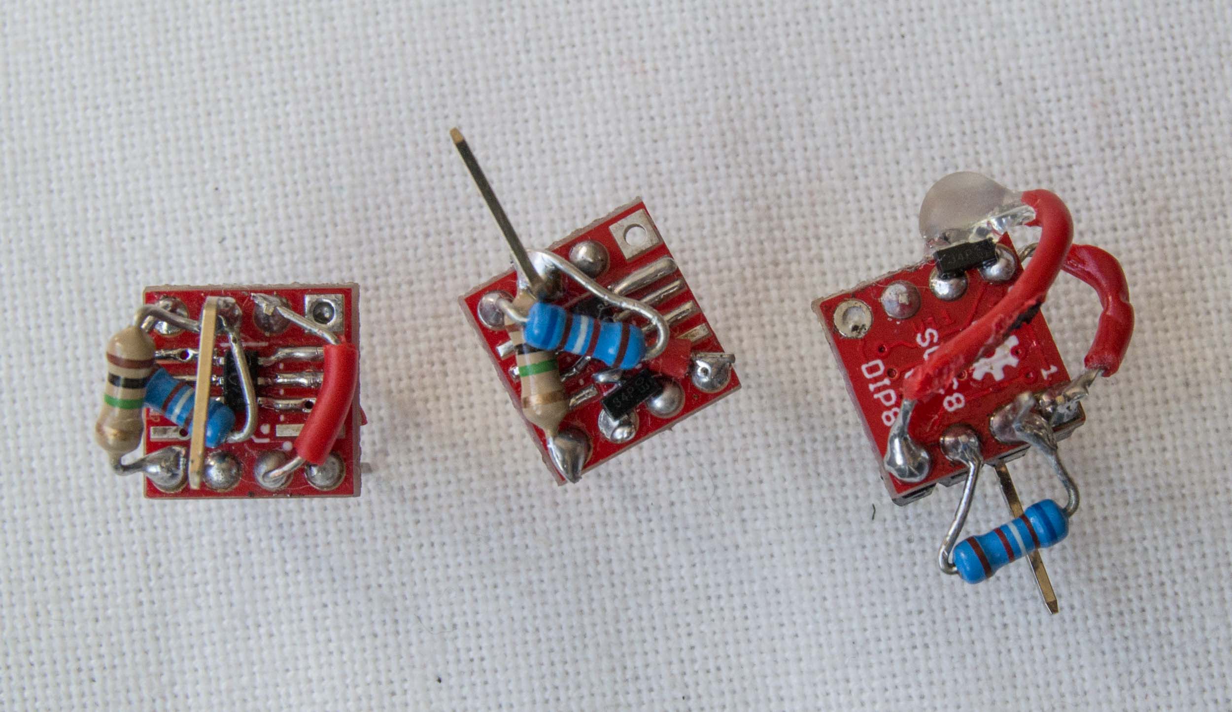
Figure 2. This is most of what you need to allow an Arduino-based data logger to last for many months on small batteries.
.
Table of intervals. A resistor of the listed resistance will produce the indicated logging interval.
| Interval | Resistance |
|---|---|
| 1 Second | 5.2 KΩ |
| 2 Seconds | 6.79 kΩ |
| 3 Seconds | 7.64 kΩ |
| 4 Seconds | 8.3 kΩ |
| 5 Seconds | 8.85 kΩ |
| 6 Seconds | 9.26 kΩ |
| 7 Seconds | 9.71 kΩ |
| 8 Seconds | 10.18 kΩ |
| 9 Seconds | 10.68 kΩ |
| 10 Seconds | 11.2 kΩ |
| 20 Seconds | 14.41 kΩ |
| 30 Seconds | 16.78 kΩ |
| 40 Seconds | 18.75 kΩ |
| 50 Seconds | 20.047 kΩ |
| 1 Minute | 22.02 kΩ |
| 2 Minutes | 29.35 kΩ |
| 3 Minutes | 34.73 kΩ |
| 4 Minutes | 39.11 kΩ |
| 5 Minutes | 42.90 kΩ |
| 6 Minutes | 46.29 kΩ |
| 7 Minutes | 49.38 kΩ |
| 8 Minutes | 52.24 kΩ |
| 9 Minutes | 54.92 kΩ |
| 10 Minutes | 57.44 kΩ |
| 20 Minutes | 77.57 kΩ |
| 30 Minutes | 92.43 kΩ |
| 40 Minutes | 104.67 kΩ |
| 50 Minutes | 115.33 kΩ |
| 1 Hour | 124.91 kΩ |
| 1 Hour 30 Minutes | 149.39 kΩ |
| 2 Hours | 170 kΩ |
1 Comments
Amazing Christian!!!
Reply to this comment...
Log in to comment
Login to comment.