I've been working on this
Mostly unrelated and relatively dangerous
project over the past week building a small capacitive discharge welder.
BackStory
Hi, my name is Kina and I do sensor and datalogger development for with the University of Alaska in Fairbanks. I've been working with folks on some tree physiology projects which I'll post about in another note later. I've just started working on designing some Sap Flux sensors to measure the rate of flow of liquid in a tree. I'm going to be using the Granier Method, which requires two temperature sensor probes and a small heater coil to be embedded into the tree. The flow rate can then be calculated from the temperature difference between the heated probe and the ambient probe. This method uses tiny little thermocouples made from 0.005" dia wire inside of 18 gauge needles. ...so we need to make thermocouples.
What is a thermocouple?
There are a multitude of different temperature sensors out there in the world. Thermistors are ones that are commonly mentioned around here which vary resistance based on temperature. Thermocouples are different in that they consist of a junction between two different types of metal alloy which generate a small electrical potential as their temperature changes. Attached to a special amplifier, you can get accurate temperature readings across a very wide range. They can also be made from wires smaller than a human hair (which respond very quickly to temperature changes) and because they operate because of the Seebeck Effect they can be used to cool if charge is applied to them. Neat!
So why the welder?
Well, soldering thermocouple wires isn't great. Solder doesn't like to stick to them, it also adds a filler metal which affects the response of the junction and adds thermal mass to it, and if you're trying to measure temperatures above the melting point of the solder....yeah, that won't work. So welding them is the ideal....but thermocouple welders cost thousands of dollars and all they are essentially is a bank of capacitors, some big MOSFETS for discharging them and microcontroller to time the discharge.
The Welder
I did some quick googling. There isn't much for DIY thermocouple welders, but there sure is for capacitive discharge welders for welding tabs onto batteries. And they're the same thing. Hackaday has a some nice projects, but instructables has one project which is nicely documented. There is also this one where I got most of the beta for this project.
The whole system is pretty simple and consists of 2 parts.
Energy Storage
The energy storage is a capacitor bank which is charged by a variable benchtop power supply. I used 24 47000uF 25V capacitors arranged into 8 groups of 3. The capacitor bank is discharged through 16 power MOSFETS (2 per group) into some aluminum buss bars I made. The MOSFETS are controlled by the control system.
The Control System
The control system is an arduino (I used a pro mini I had laying around), a button, a turny knobby thing, a small screen, and a MOSFET driver chip. The control system is powered from a 9 or 12v wall wart I had laying around (there is a theme here). A button triggers start of the discharge and the arduino controls the timing of it. Pretty simple.
The Build
Total cost was around $300 for parts I didn't have laying around. The majority of that was the capacitors and the MOSFETS.
I was able to make my own circuit boards because I own some fancy toys (like a small CNC mill), which made this project a little cheaper.

The Buss Bars were made from 0.5" square aluminum stock with drilled and tapped holes to match the circuit boards.

The MOSFETS in between the Busses nicely. Each board plugs into the next one passing along the Trigger signal and balancing the charge across the capacitor bank.

These are the rest of the capacitor boards ready for assembly.

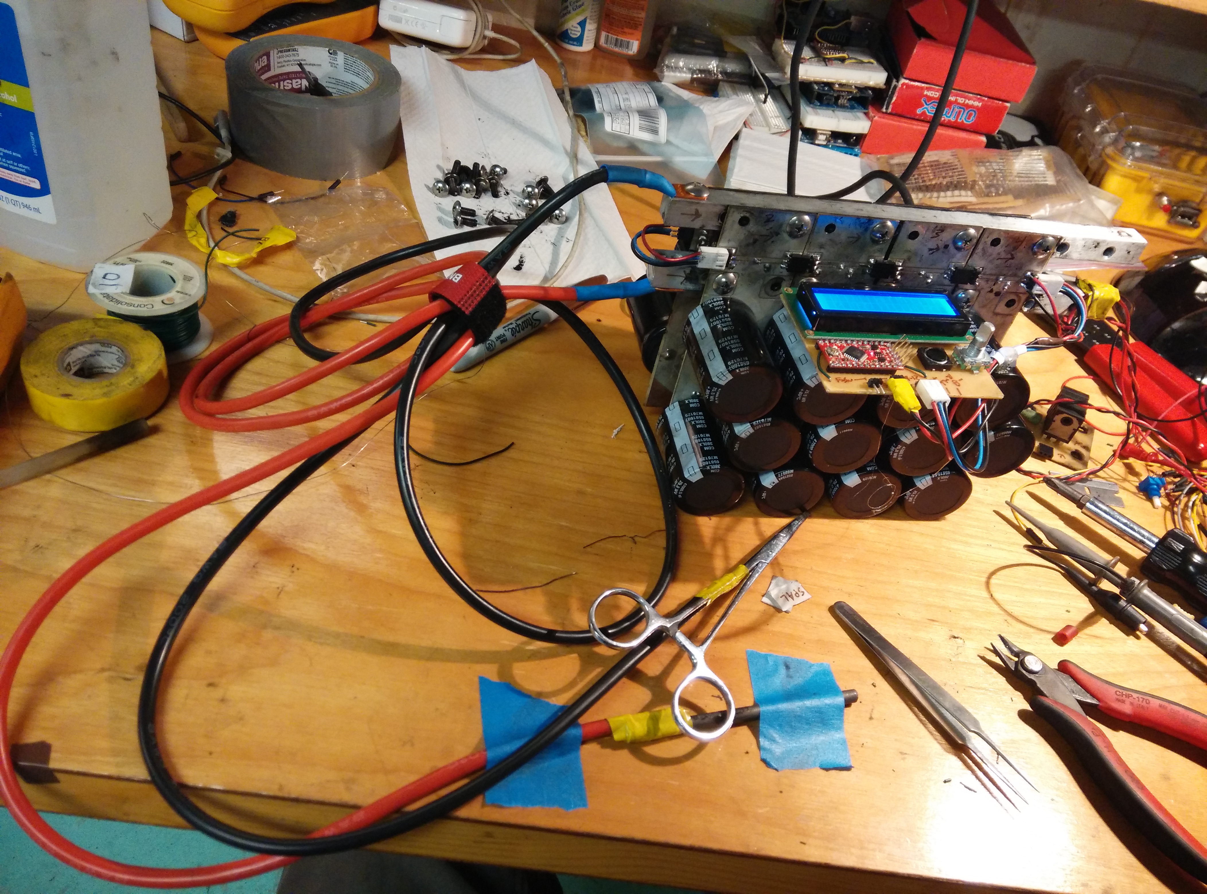
This is assembled capacitor bank. The little board on the end was an array of diodes to protect against flyback voltage due to discharging huge current spikes across an inductive load. I may have designed it up wrong or something because it caused weird biasing issues with the MOSFETS and I ended up just removing it. I tested for voltage spikes using an oscilloscope and didn't see any issues, so it's fine. There was also a large resistor to drain the capacitor bank when everything is shut off to mitigate surprise electrocutions.

This is the final testing phase...Just don't touch the sparky parts and you'll be fine. The positive lead is stripped and taped to a round carbon rod and the negative lead is stripped and taped to a set of locking hemostats that, guess what, I had laying around!

I ended up just dropping the whole thing into a cardboard box and hot gluing the control board to the top for now. I don't have time for fancy cases and I don't feel like this isn't that much of a fire hazard.

Results
Are positive. It welds. And it actually welds pretty good thermocouples that actually work! I've been testing on 0.015" wire with great results.


VID_20160712_111719 from Kina Smith on Vimeo.
Other Uses
With different electrodes this would be magic for welding battery tabs. It works great for vaporising screwdrivers (oops). Chris Fastie also suggested it might be really useful for use with the #spectrometer for analysing metal contents by creating an electrical arc on the metal and capturing the spectra from it.
Documentation
The code and PCB files are on Github. If you want to try building this, please let me know. I would be happy to provide some better system schematics and technical help.
7 Comments
Ha, this is very cool, its like a turbo charged tack welder!
Reply to this comment...
Log in to comment
Nice job mitigating those surprise electrocutions. Keep it up.
How does the weld actually work? What is the blob of "new" metal (the weld) made from? Can you file that down into a point?
I guess you have to calibrate these thermocouples. Or do they just work because science?
Very impressive achievement. Great post.
Chris
Is this a question? Click here to post it to the Questions page.
Reply to this comment...
Log in to comment
How I'm doing it now is holding the two thermocouple wires in a pair of locking hemostats connected to the ground terminal of the welder. There is a graphite electrode connected to positive. I touch the ended of the wire to the electrode, press the button to discharge the capacitors and it makes an arc across the ends of the wire to the electrode, either melting tips of the wire, or vaporising the whole thing. One little thing that is kind of an issue is that the two wires are different alloys and have slightly different melting points/conductivity so the weld isn't uniform...and sometimes the wires don't actually weld together, just melt on the ends. I'm working with really fine wire (0.005" - 0.001" in diameter) so making points isn't really an issue. The thermocouples work off of established physical properties of metals....So while some calibration is obviously going to be needed, I think they are probably pretty close as is. Because I'm not soldering the wires together they'll probably be more accurate because there isn't a 3rd alloy in there muxing things up.
Reply to this comment...
Log in to comment
That graph looks like a sketch of what would happen if you made a mistake.
Reply to this comment...
Log in to comment
looks great and usefull. I made a very, very dangerous and poor quality spot welder in high school by chaining the capacitors found in disposable cameras in parallel up to a single disposable camera charge circuit, and then adding a higher current power supply than a single AA cell. worked great for 20 gauge wire and smaller. it eventually melted its circuit board. It also nearly stopped the hearts of me and several friends in accidental discharges.
Reply to this comment...
Log in to comment
Here is another way to weld thermocouples: https://publiclab.org/notes/Vern/10-30-2017/making-thermocouples. I'm not sure which method is more responsible.
Reply to this comment...
Log in to comment
Hi, I'm making a project just like this to a professor in my college. I need to make a welder to join thermocouples. I clicked in the link to Github, but I wanted to know if you have a list of the materials used. And what program should I use to open the schematics correctly? Thanks!
Is this a question? Click here to post it to the Questions page.
Reply to this comment...
Log in to comment
Login to comment.