Purpose
This is a general guide to putting together the Simple Water Sensor Kit, described in Designing A Simple Water Sensor Kit.
The Simple Water Sensor platform is a system for collecting water quality data using the DF Robot series of liquid sensors.
The platform runs on an Arduino Micro. It outputs and displays data readings using a single flashing LED and sends data to a computer or smartphone/tablet over USB by emulating a keyboard.
The goal of this project is to have a basic design for cheap, easy to build, water quality sensors that can be used to log quantitative data without requiring additional software, drivers, or a complicated circuit.
In order to begin collecting data. you just plug the sensor into your computer with a spreadsheet open and turn it on -- it will begin typing out the sensor readings on your screen.
All of the DF Robot liquid sensors (and many other Arduino-based sensors) share a common basic interface. This page will be a general guide covering the process and aspects of setup that are common across all of the sensors. I will put specific guidelines on the use of individual sensors in separate research notes.
- Turbidity Sensor
- pH Sensor
- Electrical Conductivity Sensor
- Dissolved Oxygen Sensor
- ORP (Oxygen Reduction Potential) Sensor
- TDS (Total Dissolved Solids) Sensor
This series will not address any issues around logging data or deploying these sensors in the field. These issues should be addressed but this series is about the basic process of building the kit and connecting it to your computer.
This is a prototype project, so we would very much appreciate any thoughts or feedback you have on the design or documentation, as well as on how you might want to use these kinds of water quality sensors in your own projects and campaigns.
Materials needed
- Your sensor of choice This is the sensor that you have picked to collect your data. Sensors covered in this series are:
- Mini-Breadboard - $6.98 for 6 (Amazon)
- Arduino Micro - $18.89 for 3 (Amazon), $4 (Ebay)

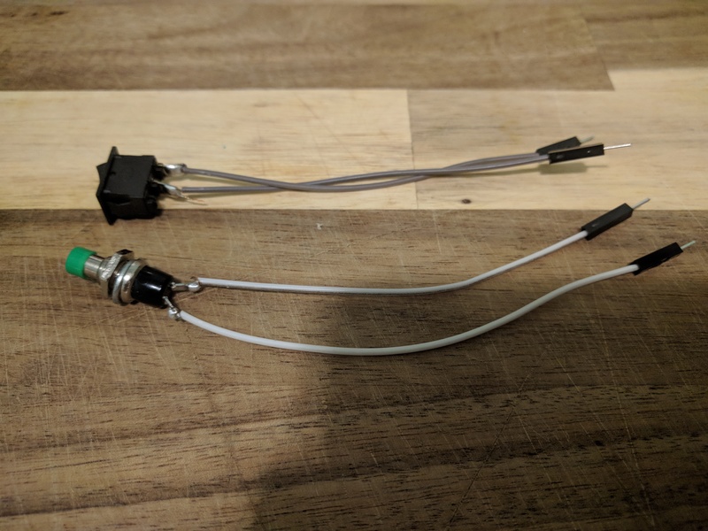
- Switch or Button - $7 for 15 rocker switches (Amazon), $8.29 for 12 push-button switches (Amazon)
- 4 Male to Male Jumper Wires (Red, Black, Blue, Green) - $9.99 for 80 -- assorted colors (Amazon), $6.55 for 100 with choice of color (AliExpress)

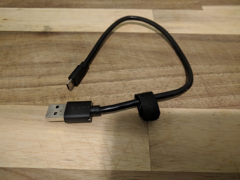
- USB Micro Cable - $7 for 3 (Amazon)
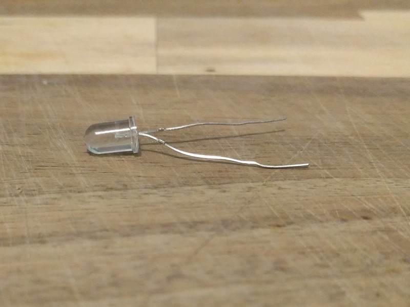
- An LED - $6.55 for 100 (Amazon)
- A laptop, smartphone, or tablet with a USB port to plug in the sensor
- A USB "on the go" cable (if using a phone/tablet) - $5 for 3 (Amazon)
Part A - Assemble the Sensor Platform
Step 1: Attach Arduino Micro to Breadboard
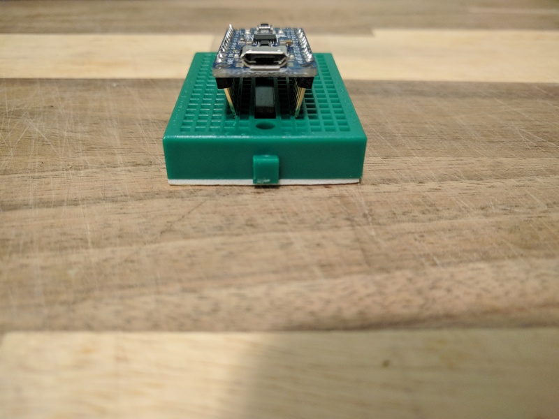
The Arduino Micro has two rows of "header pins" coming off of the bottom. These pins can fit into the sockets in your breadboard.
The Arduino has two rows of header pins. The breadboard has a break down the middle. Insert the Arduino so that the rows of pins are on opposite sides of the break.
Step 2: Attach the On/Off Switch
Your On/Off switch should have two wires coming off of it. Each of these wires are going to go into the breadboard to connect the switch to specific pins of the Arduino.
Connect the switch to the "GND" and "10" pins on the Arduino by inserting the wires into the sockets in the breadboard next to the pins that have these labels.
](/i/37558.jpg)
Both of the wires are the same and it doesn't matter which wire you connect to which pin.
Step 3: Plug in the LED

The LED has two legs, one longer, one shorter. They should be connected as follows:
| Arduino Pin | Label | LED Leg |
|---|---|---|
| Digital I/O Pin 2 | 2 | LONG |
| Ground (-) | GND | SHORT |
If the LED is plugged in backwards it will not light up.
Step 3: Connect Sensor Wires to Arduino

We will use the Male to Male jumper wires to connect the Arduino to the sensor by plugging them into sockets on the breadboard. The pins on the Arduino are labelled on the circuit board. We will connect the wires as follows:
| Arduino Pin | Label | Wire Color |
|---|---|---|
| Power (+) | VCC | RED |
| Ground (-) | GND | BLACK |
| Analog 0 | A0 | BLUE |
The BLACK wire can be connected to any of the "GND" pins on the Arduino. In this photo I have connected it to the same "GND" pin as the On/Off switch by plugging it into another socket in the same row of the breadboard.
When we are ready to attach our sensor we will do so by plugging these 3 wires into the sensor's circuit board.
Step 4: Connect the Sensor-Select Jumper Wire
This kit is designed to be used with any of the different DF Robot Liquid Sensors and comes pre-loaded with software that can collect data from any of them.
This software needs to know which sensor you have plugged in, though, and it can't figure it out itself. To tell it what sensor we are using we will connect a jumper wire from "Pin 3" on the Arduino to one of the other digital i/o pins.

In this photograph I have the green sensor-select jumper wire from Pin 3 to Pin 4 in order to select the "Turbidity Sensor." See the chart below:
| Sensor Type | Arduino Pin # |
|---|---|
| Turbidity | 4 |
| pH | 5 |
| Conductivity | 6 |
| Dissolved Oxygen | 7 |
| Oxygen Reduction Potential | 8 |
| Total Dissolved Solids | 9 |
Part B - Assemble and Attach the Sensor
This is an overview of how to attach the DF Robot sensors to the Arduino. For sensor-specific instructions see the DF Robot wiki as well as our guides for individual sensors:
- Turbidity Sensor wiki
- pH Sensorwiki
- Electrical Conductivity Sensor wiki
- Dissolved Oxygen Sensorwiki
- ORP (Oxygen-Reduction Potential) Meter wiki
All of the DF Robot sensors have the same basic interface. They consist of: - A Sensor Probe - A Circuit Board - Wires and Plugs
Once you have the correct wires plugged in there will be 3 wires coming from the sensor circuit board that we need to connect to our Arduino. They will be RED, BLACK, and BLUE. Each of these wires needs to be connected to a specific pin on the Arduino.
- The RED wire is for the POWER connection. It needs to be plugged into the pin labelled 5V.
- The BLACK wire is for the GROUND connection. It needs to plugged into one of the pins labelled GND.
- The BLUE wire is the DATA or SIGNAL connection. It needs to be plugged into one of the _Analog Input _pins on the Arduino. We will generally use the pin labelled A0 unless the sample code provided with the sensor uses a different pin.
The RED and BLACK (POWER and GROUND) wires connect the sensor to a power supply so that it has the electricity that it needs in order to run. The BLUE (SIGNAL) wire is the wire that sends an electrical signal from the sensor corresponding to the turbidity in the liquid.
Many sensors you use will follow this pattern of having a POWER, GROUND, and SIGNAL wire and will be wired up in much the same way. The main things you have to do differently for different sensors are:
- Make sure you have the right voltage (5 volts or 3.3 volts based on the sensor)
- Understand how to interpret the signal that you get from your sensor
Part C - Program the Arduino
If you got this project as a kit, hopefully you received a pre-programmed Arduino. If so, you can skip this step. Otherwise, you will need to use the Arduino IDE to send the correct code to the Arduino.
Source code for the project can be found in our github repository.
You can also look at it on Arduino Create below:
You can copy and paste it into the Arduino IDE and hit the "upload" button. For more information, see my [note on testing and setup of the Arduino](https://publiclab.org/notes/wmacfarl/10-22-2019/how-to-set-up-and-test-an-arduino).
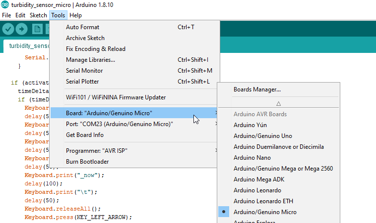
Note: if you are using the Arduino Micro you will need to choose either "Arduino Micro" or "Arduino Leonardo" as your "Board" in the "Tools" menu.
Part D - Test the Sensor
If you just want to see if the sensor is working, you don't need to turn the switch on to send data back to the computer, you can just look at the LED, The LED will blink faster with higher turbidity.
If you want to collect data, you just need to open up any spreadsheet software, place your cursor on whatever cell you want to start typing into, and then turn the switch on. It will type out a table that looks like this:
Addendum - Calibration
All of these sensors require calibration to get really accurate data. Information about how to calibrate the sensors can be found on the DF Robot wiki pages for the various sensors.
The normal way of calibrating the sensors requires you to change parameters in the software. The basic procedure is to acquire a liquid with a known value for the parameter you are testing for and then modify one or two "offset"-type variables in the code until the data provided by the sensor matches the known value of the liquid.
Without calibrating the sensors, the data you get from the sensor should be useful for making comparisons to other data from the same sensor, but shouldn't be treated as an accurate measure of the parameter in question.
Addendum: To-Dos
We should come up with a way for people to calibrate their sensors without needing to change any values in the source code.
The program for each sensor just takes a voltage value and does some math on it. At the moment this math is being done by the Arduino and then typed out into a spreadsheet, so various calibration values have to be set in the Arduino program.
But there is no particular reason why the math should be done by the Arduino. A better way to do it would be to pull all of the math out of the Arduino program and put it into spreadsheet formulas.
Then we could make a spreadsheet with the correct formulas and calibration instructions for each sensor.
Addendum - Further Questions and Considerations
- Calibration instructions+spreadsheet for each sensor
- Usage guidelines+pitfalls for each sensor
- Guidelines for making sense of data for each water quality measurement
- Useful designs for body/housing for various sensor form-factors and use-cases
And there are probably lots of other problems and things to improve on. I would love any feedback, thoughts, or questions you might have.

0 Comments
Login to comment.