Abstract
From discussion with @abdul of PLab Kits, it appears there is an opportunity for improving a "paper and tape" only mechanical assembly for the PLab 3 basic design. If the present mixed paper, tape, velcro and wood design could be simplified (and, perhaps, add a litle improvement to stability) the revised kit might find a lower-cost market niche for educational users. I took that as a challenge, spent a couple hours tinkering with design ideas and then 30 min to build this mock up.
Concepts
Paper can form a very strong, light-weight structure depending on the geometry. Recall, that by keeping the optical components (the slit, slit-mount, support base, diffraction grating (DVD), camera and mount all tightly connected, the resulting visible spectra will be more stable and less influenced by the light-tight cover. Remembering that tubes and I-beams are great examples, the first step was building a stable platform for the optics.
Note: Since this is a mock up, there is certainly room for improvement and more accurate dimensions. Some parts might be combined if laser-cut material is used and even the two wood forms might be eliminated if the stiff black paper was suitable for being pre-scored along fold lines. That might make a really light-weight, very low cost, very easy shippable educational device. While not as stable or rugged as the "wood upgrade" mock up, this version weighs only about 25 grams -- about 1/3 the weight of the wood upgrade.
Construction

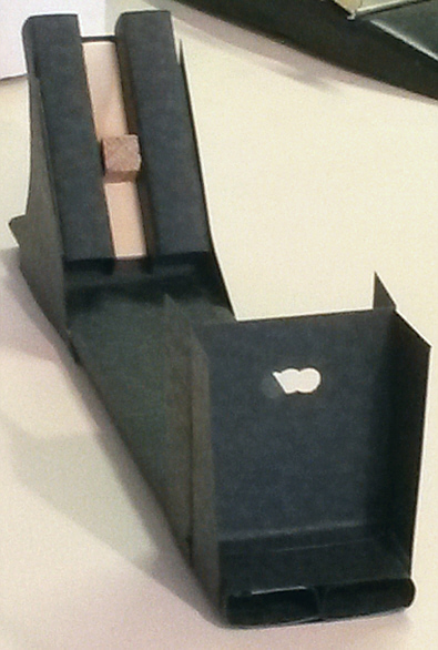
Above, and below, are shown two strips of stiff black paper (~8.5 x ~2.5 in) which is tightly folded about a 1/4 x 3/4 x 9 inch wood form. Double-stick tape is affixed to the edge which will wrap-around to form a tube.

Below, one of the identical tubes has double-stick added to the "1/4-in wide inside edge" and both have double-stick on the remaining free surface.

Next, the cover-slip of the inside tape is removed, the other tube is turned over, the two are carefully aligned and then pressed together. The remaining two 1/2-in wide tapes are stuck by simply pealing-back the cover-slip while the two tubes are close-fit. Alignment is guaranteed because the internal tape is holding the two tubes together. The resulting double-tube is quite rigid and resists twisting -- because of the tubular shape and because adjoining surfaces are prevented from sliding with respect to each other.

Next, the slit-mount is constructed from two identical folded pieces of the same stiff black paper (~2.5 x ~2.25 in). The same 1/4-in double-stick tape and mounting techniques are used so that it is easy to keep everything aligned. (For 1/4-wide tape, I simply split 1/2-in tape with Teflon-coated scissors.) The slit "exposure" port was simply formed with a hand hole punch; it is not critical as the slit does the real work.


The next two images show the construction of the camera and DVD grating support. Again, this uses a tubular design but with a 1/2 x 1/2 inch wood form to tightly wrap the stiff black paper (~5.5 x ~2.5 in) into shape. Again, 1/2 in double-stick tape secures the shape of the two tubes (which will support the grating) on either side of the mounting surface for the camera.


Next a simple square is cut from black paper (~2.5 x 2.5 in) and then cut diagonally to form a 45-deg angle and the side supports which will hold the camer/DVD mount.


The camera sub-assembly is then fixed to the previously-assembled tubular support and the camera can then be mounted.

0 Comments
Login to comment.