Abstract
This is a continuation of my series on spectrometer noise which now focuses on observations of a CFL spectra in attempting to more clearly identify the spectrometer's noise source(s) while searching for a practical methodology for improving spectral measurements. The best option appears to be time-averaging of pixel data as there appears to be little correlation between the observed noise and any other independently measurable parameter.
References
PLab 3 Spectrometer Upgrade Prototype
Spectrometer DVD-Alignment Auto-Correction
Disclaimers
While significant efforts were used to assure stability and to write algorithms for the general case, these tests and the acquired data only represent a limited subset of testable light sources and possible user configurations.
Configuration
Again, I'm using my V3 prototype along with a 14W, 900 lumen 2700K CFL. However, to eliminate the possibility of any added mechanical-related noise, I replaced the film-based ND filter / attenuator with a baffle containing a small hole; mounted next to the lamp. The hole diameter and distance allowed precise setting of the signal intensity just below clipping but without any optical interference. All components were mounted on the same bench and nothing was disturbed during the 15-min data acquisition period.
Data
I enhanced the data acquisition to include 27 camera pixel lines per frame; 1) 3 lines at 100 lines above the spectral band, 2) 21 lines within and centered on the spectral band, and 3) 3 lines at 100 lines below the spectral band. All data was collected and saved to 15 data files each containing 1 min of data at 5 samples per second. The added 3 lines above and below the spectral band allowed for observing the camera's dark field to look for drift, noise and any other anomalies. Having saved all data to files, post-processing with Matlab becomes significantly easier than working in real-time.
Observations
First, I looked at the dark field to observe the relative background noise level and look for any obvious DC drift component. While there is some noise, it is relatively small and there is little indication of a significant offset bias.

However, the above data is over only a single sample in time, so the next plot shows how this data changes over time. The plots show the background noise is consistent and there does not appear to be significant long-term drift.

Given that the Solux test data showed much more significant noise, and if the background noise is not a major issue, then how does the CFL spectra compare? The following plot shows the CFL spectra contains significant noise like the Solux spectra.

Analysis
So, let's take a closer look at the central green 546 peak. Notice that while the ends (near zero intensity) have small residual noise, the peak as considerably more noise which will easily affect measurements.

This invokes several thoughts; one of which is to look at the 546nm peak noise (as described by a single pixel) and the intensity detected by the two pixels on either side of 546nm. In the plot below, it is easy to see that just one pixel describes to center of the peak as the level of the neighbor pixels are only about half.

The above plot covers 91 samples so represents about 20 sec and the peak intensity varies by nearly 20%.
So, what about the neighboring pixel lines (above and below the center line of the spectral band), each of which should be detecting nearly-exactly the same signal because (at least visually) the spectral band seems uniform across many lines.

The above plot shows the 546nm pixel data from 3 parallel lines over the same set of samples as the above plots. Notice that any hint of correlation between the pixel data over time, is very weak. The lower plot clearly shows mostly random error, which again, is in the range of 10-15%. Clearly, the noise of each pixel is nearly independent from every other pixel.
So, what about noise differences between different peaks. The plot below compares the peaks at 436nm and 546nm; they each have just about the same percentage noise and show no correlation with each other.

Finally, is there some value to be derived from observing a long-term average of a spectra? The plot below shows the effects of a 61-point running average on 300 samples of 546nm peak data. Yes, a slow drift is recognizable but it does not appear periodic.

Hypotheses
All of these observations support the following hypotheses:
1 - Noise from pixels is inherent to the inexpensive webcam and independent from every other pixel.
2 - The observable long-term drift is the most likely source of that specific 'noise' component which could be related to an AGC effect. Most probably, the higher frequency pixel noise is completely outside the loop bandwidth of any AGC.
3 - There is no particular advantage to averaging parallel lines of pixel data as their detected noise appears uncorrelated.
4 - Collecting and analyzing background noise data is certainly possible but, since it is not correlated, would not likely help with noise reduction. However, it might still provide background DC offset correction; especially in higher ambient light conditions.
5 - Time averaging of pixel data holds the best option for spectra noise reduction. Averaging data across wavelengths from a single scan line has a low-pass filter effect and therefore damages spectral features with high transition rates (sharp peaks). However, averaging pixels over time, removes time-based noise without removing the sharp transitions of the spectra.
A Solution?
The following plot demonstrates this effect. Both curves were processed through 15-point averaging but: A) the Blue curve resulted from filtering 300-800nm spectral data from time sample #6 whereas B) the Red curve resulted from filtering each pixel value over 15 samples. The negative effect on the CFL spectral details is easy to see.

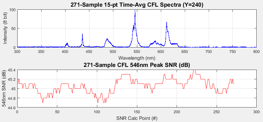
The next plot shows a 15-point (3 sec at 5 fps) running average, implemented over a 271-sample period of nearly a minute. The upper plot looks surprisingly sharp considering that all 271 time-averaged spectral plots have been written over the top of each other -- meaning, all 271 spectra are very similar as a result of time-averaging and spectral detail appears well preserved.

4 Comments
Looks like at least there are no "bad" pixels as they all show about the same amount of noise.
The time averaging seems to achieve a very sharp-peaked plot. Looks nice and accurate. Can you reproduce this exact sharp plot with the same setup a few days later?
Is this a question? Click here to post it to the Questions page.
Reply to this comment...
Log in to comment
Or, they are all 'bad' (noisy) to some degree ;-) The sharpness of the peak is still mostly a factor of slit, mechanical rigidity, being light-tight, etc. The last plot which shows (blue) so many separate spectra overlapped is a good indication of repeatability and my prototype has been consistent over time. The one detail that this data has observed is the detail of sharp peaks where noise and the fact that the peak is defined by just 1-3 pixels. The time-average method helps preserve that detail by avoiding averaging of a single frame's spectral data which tends to smear out the spectra.
Reply to this comment...
Log in to comment
Great post! I love how you so clearly stated some of the conclusions.
A few thoughts:
But if we saw the same data, but the lines were connecting points as in this graph instead:
we'd see a series of time graphs per wavelength for the whole spectrum. Just curious!
Thanks, Dave, my biggest takeaway for this note was your point that since noise is truly uncorrelated (dare I say random, maybe not), subtracting black noise from the whole spectrum won't work.
Is this a question? Click here to post it to the Questions page.
Reply to this comment...
Log in to comment
@Warren, thanks for the suggestions. Take a look (above) at the two new plots which replace the one(s) you referenced. You're right, the new ones make the data easier to visualize. When I did the more simplistic plot, and discovered the nature of the noise at the peak, that led me toward other observations so that plot was sufficient to know to look elsewhere -- but the reader doesn't necessarily follow that thought trail. Matlab has very good plotting; it just takes a bit more effort and care to get the fancier plots. I'm not discovered a way to do opacity, but the 3D shaded mesh is a good alternative.
Yes, I believe the noise is all unvorrelated noise. What surprised me was that neighbor pixels, in X and in Y appeared random with respect to each other so I don't see a way to subtract anything other than looking a long-term averages and assuming it is a DC offset -- though that offset is much smaller than the noise so that error is small compared to the residual from just averaging so much noise. The biggest gain is obtained by averaging pixels in Time but NOT averaging pixels across a spectrum -- which retains fidelity of the spectra signature.
I also looked at performing a 'peak-hold' operation over time on the spectra, but, alas, that affect both signal and noise, so the calculated SNR actually goes down. Peak-Hold is used in spectrum analyzers but it is primarily of benefit when there are transcient peaks that need to be captured. That said, peak-hold could be a good feature to add -- it's just not so useful for noise reduction.
Reply to this comment...
Log in to comment
Login to comment.