What I want to do
I got inspired from this post on checking oils spills posted earlier. What inspired me was the idea of making the spectrometer portable, and specifically the light source portable as I thought the idea of using a laser pointer was very clever. Starting from there, I wanted to try and build a rig for prototyping a system that could allow for swapping different LEDS in and out on a tablet running spectral workbench.
My attempt and results
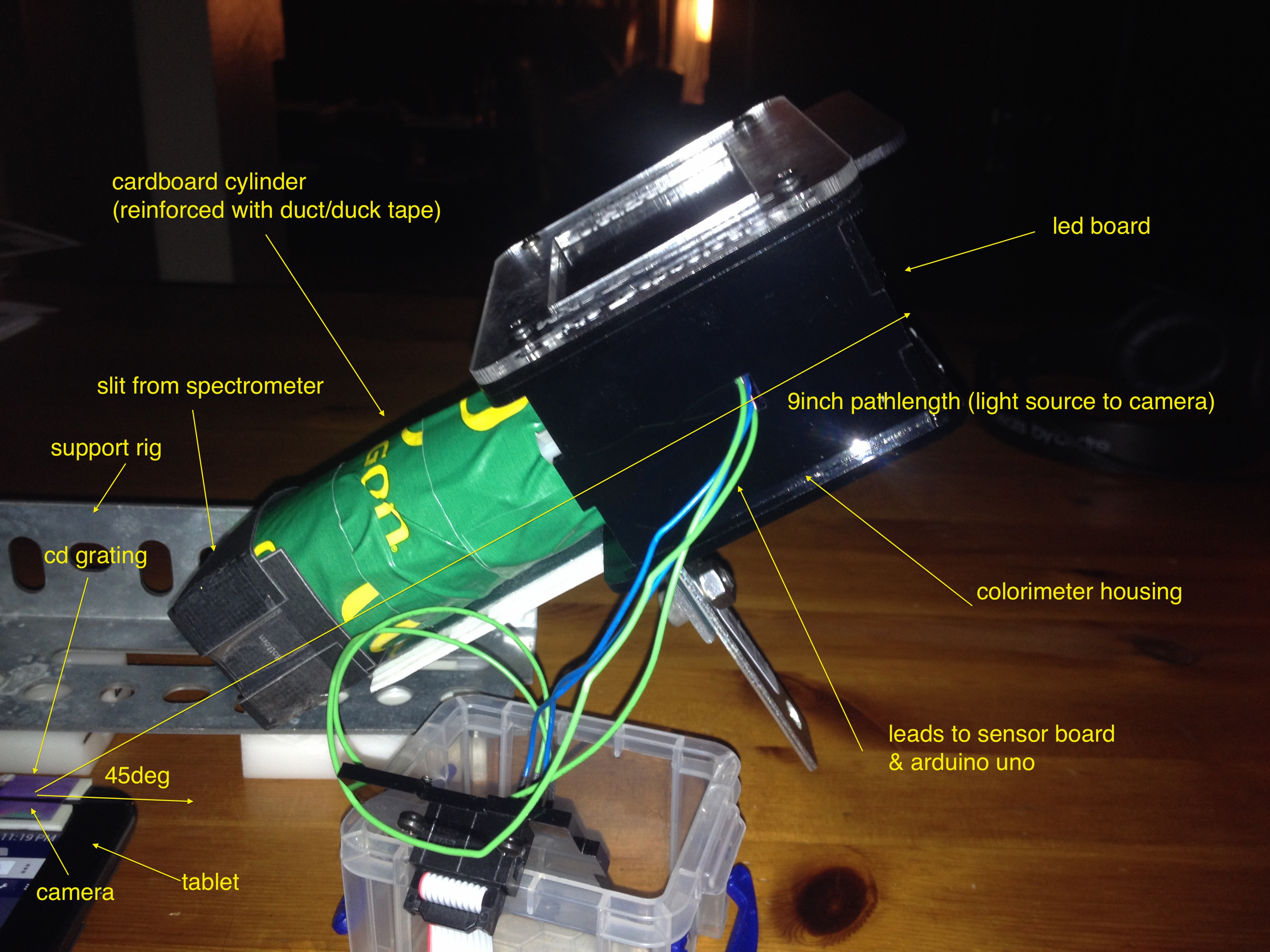
I took the grating and the slit from my PublicLab spectrometer. I mounted the grating (the piece of CD) over the webcam on a 7" Samsung G2 Tablet using two small pieces to double-sided tape. I then assembled a support and I mounted my IORodeo colorimeter at a 45 degree angle and pointed it towards the camera on the tablet. I removed the sensor wall from the housing so that side was opened up. I then took a cardboard cylinder and covered it with some duct tape (or duck tape) to reinforce it and mounted it into the housing of the colorimeter.
Test Rig

Full Setup

Once I got the structure in place, I could adjust the angle of the light using the test rig to adjust the angle at which the light was directed at the camera. I did this using a level app on my phone and adjust a set screw on the bracket used to support the light source.
I was able to come up with a way to operate the LEDs using the tablet directly by using an app to write commands to the usb port and connecting the arduino to the tablet using an OTG cable. The OTG cable puts the tablet into something called "host" mode, which means that it can control periphery hardware you hook up to it. It also provides power to all the circuitry required to run the LED board, so batteries are not needed. I found that if the tablets battery level drops below a certain point that (~50%) that the OTG cable will not power the arduino, and thus the LED board cannot be controlled.
To set up the LED board, I used the app USB Serial Monitor Lite, which can be found on Google Play (its free). When you plug the OTG cable in and turn the app on, it should recognize the board right away. If not, select "Open Device" from the menu.
The amount of time the LEDs are on can be controlled up to ~5 seconds. I found that if I set the LEDs to be on for 5.5 seconds, the board stalls out. This is perfect as it leaves the LEDs on, making it easier to set up and get a good measurement.
To set the time, send the following command over the usb port:
"[2,55000]\r"
This will stall out the LED allowing you to work.
To turn on an LED, send the following command over the usb port:
RED - "[9]\r" GREEN - "[10]\r" BLUE - "[11]\r" WHITE (RED, GREEN, BLUE on all at once) - "[12]\r"
Once an LED is on, I went to using Chrome on the tablet and collected spectra. This is what I got.
Red LED

Green LED

Blue LED

White LED (Red, Green, Blue on all at once)

Questions and next steps
I was able to get what I wanted for a first pass. The test rig will allow me to make adjustments to the pathlength (distance from camera to light source) to see if I can modulate the intensity, as I found the Blue LED to be pretty weak compared to the Red and Green LED using the same setup. I referenced some previous data I had testing the same LED board using my normal PublicLab spectrometer setup, but I found that I was saturating the signal (which means the pathlength is to short). Based on my notes, I was running at 5" for some reason (?).
I'm a little concerned that if I were to want to make this truly portable, that a 9" pathlength is too long. I plan to use the test rig to explore how much I can reduce this by. I will also check a few different angles to see if there is an optimal point (like, somewhere between 40-50deg).
I need to build a shroud so I can work on this with the lights on, as the the current setup allows to much ambient light in to get meaningful data.
The only other thing I want to work on is a better integration of the LED control and spectral workbench. My plan right now is to a simple Android app setup to send the command to the LEDS and imbedded spectral workbench into the app. When I get around to it I will get something up on GitHub for people to look at.
Why I'm interested
I want to build a portable light source system for use with spectral workbench. I think I can come up with a system in which different LEDs can either be swapped out easily, or an array of several different LEDS can be mounted in close proximity to use as a light source. I also want to be able to run this circuitry using the batteries from the table (or phone) as well as be able to control the LEDs directly through an app. By prototyping using this approach, it will be easier to come up with ways to miniaturize a system once the need dimensions are determined.
2 Comments
Wow, very cool. We had designed the 3D printed sample testing thingy to have space inside for a AAA battery and a small LED board. Or maybe some coin cells. The idea of powering it off the USB of the device is clever!
Reply to this comment...
Log in to comment
Oops, link to smartphone sample testing setup: http://publiclab.org/notes/cfastie/02-25-2014/mobile-cuvette-holder
Reply to this comment...
Log in to comment
Login to comment.