So what is it about
As we know there are primarily two types of barcode scanners - CCD based and Laser based. CCD based essentially contains a CCD to take a digital 'pic' of the barcode and processing it. They are obsolete now, as there must be a physical contact between the scanner and the barcode. Laser based contains a optical assembly which uses a laser beam that scans the whole barcode region with a help of a rotating mirror; a focusing mirror is used to focus the beam onto a photodiode.
Come to the point man!
So, if we can replace the rotating mirror with a piece of reflection grating (or simply paste a grating on the mirror) we already have what we need - grating, focusing mirror, detector. All we need to make is a slit, which can be easily done. I can't do it as I dont have experience of hacking electronics but I believe this is achievable by someone who could play with arduino and stuff.
Further questions
How expensive is it to get the front reflection mirror? Can it be made by normal silver salt dipping method (using for conventional looking mirror), and not painting it with a protective paint? I guess that would be very cheap method if its possible.
Finding partner
Is there anyone who would like to partner with me for a project of this kind - making a pocket-sized spectrometer. I am looking for someone adept at electronics (and may be MATLAB too).
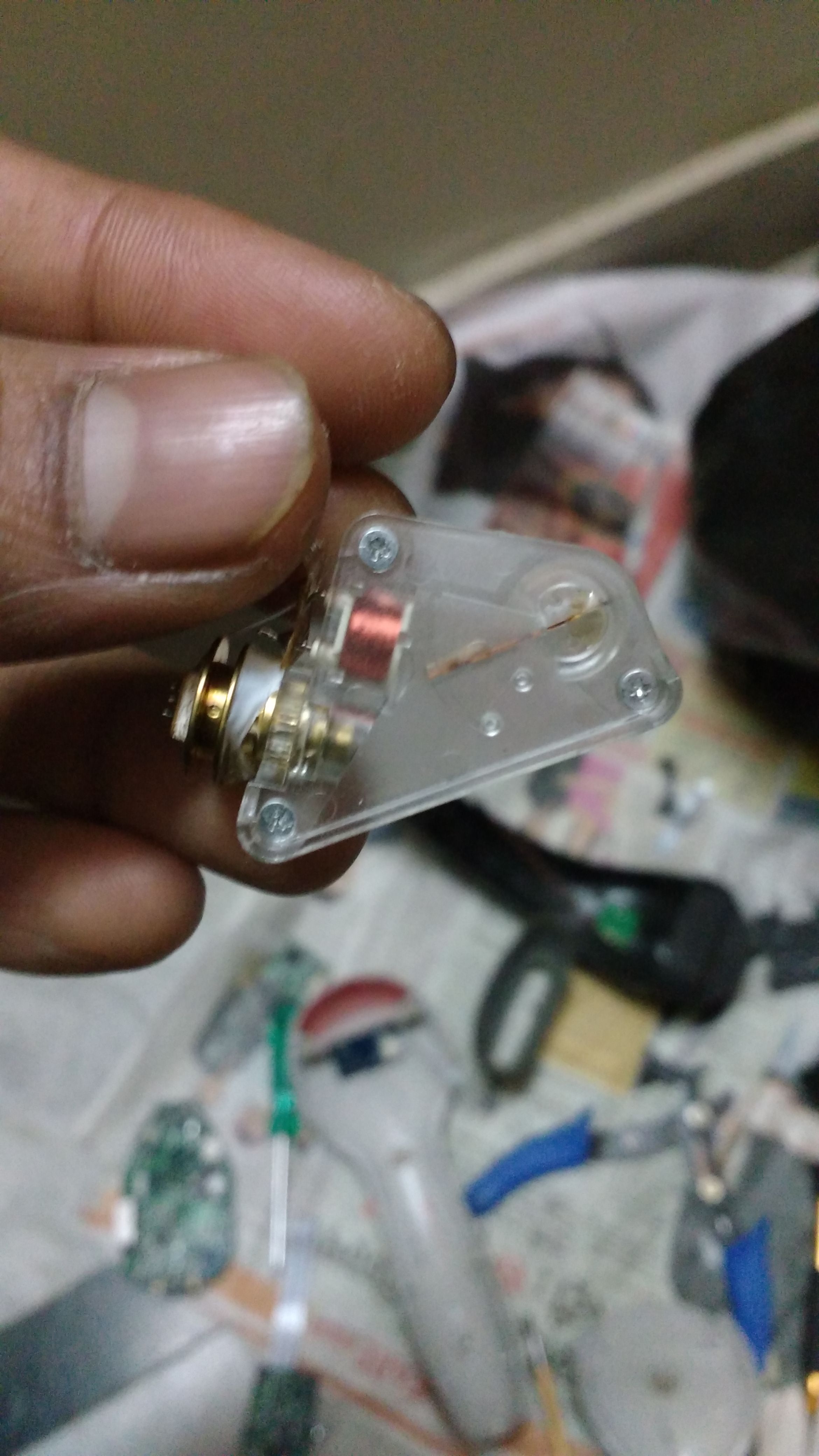
Image

About the image
It shows the optical assembly. Golden colored metal is the laser, copper colored is the motor, golden colored glasses are mirrors - plane and focusing. Steel-type container in the left side of the above image contains the photodiode.
11 Comments
Wow, ambitious! I've bought first surface mirrors here, but that may not be great for you depending on where you're ordering from.
http://www.sciplus.com/p/MIRROR-FIRST-SURFACE15MM-X-15MM-X-1MM-THKVERY-SMALL_248
so, you're going to rotate the grating, not the laser, and scan the spectrum repeatedly? Can you draw a diagram to explain, I can't quite picture it.
Is this a question? Click here to post it to the Questions page.
Reply to this comment...
Log in to comment
Neat idea, but ... Perhaps I dont understand what you are trying to do, but getting a spectrum is measuring multiple wavelengths of light and lasers are monochromatic. If you were going to replace the laser with some other light source, then you could get a spectrum.
Reply to this comment...
Log in to comment
I'm sorry if I wasn't very clear there.I DON'T mean to use laser as a source. I was just explaining the working of the scanner.
@warren (White) Light would be coming from a slit which would be situated in the 'window' part of the scanner (which points towards the barcode). Rotating the grating would allow different wavelengths of light to fall on the detector. If the motion of the grating is known, we can have a relation between angle of rotation (corresponding to the wavelength falling on detector) vs intensity recorded (of that wavelength). This is same as monochromators which are very common form of spectrometers.
@JSummers I would like to use a CCD instead of the motor assembly for two obvious reasons: No hassle to control the motor movement & no need to compute the data obtained and correlating that to the rotation. But I'm in particular impressed with the snugly fit optics on the PCB. That gives me some confidence that such tiny stuff could be made. I am trying to collect resources and information how this can be done. I'm sure everyone here is aware of Scio (https://www.youtube.com/watch?v=2C83tbuBmWY).
Sorry Warren, I didn't attached the pic, if I'm still unclear i'll draw one. BTW thanks for the link, they are quite inexpensive compared to here in India. I need to find some alternative here though.
Is this a question? Click here to post it to the Questions page.
Reply to this comment...
Log in to comment
Very cool idea!
Marking up the bottom photo with some arrows and text to identify the physical components would be helpful. I am still a bit lost on the location of several of the components you mention.
Regarding the control and data acquisition:
Clearly you will need power to the unit, any idea of the how much? What voltage and what is the current draw?
It sounds as if the mirror(or grid) will rotate much as it does now. What is driving that rotation? Constant speed DC motor? Stepper motor?
Can you identify the output of the detector? Is there a part number so one can get the spec sheet?
Control really should not be much of an issue for an Arduino or Arduino-like controller based on what you are describing. However, getting hold of and processing the output of the detector is the unknown. I am vaguely familiar with spectrometers from years ago when we were using them to monitor plasma deposition of copper on hard drive components, but I did not have to work with them on the component level, so am curious about how this might work.
The concept is great! The idea of a battery powered spectrometer that size is very attractive.
Is this a question? Click here to post it to the Questions page.
Reply to this comment...
Log in to comment
Thanks wjw. I hope they are more clear in the labelled pics attached here.
Wow, that's an elaborated response. How could I know these parameters (power required, I-V ). Source of that rotation is a drive shown in the image. Seems like solenoid to me. DC I guess (extremely sorry for these half-witted replies, I seriously have no clue of it). Detector is enclosed in a aluminium chamber. I'll take it apart in some time.
I am eyeing on the development of similar sized spectrometer using 3D printing from scratch, using CCD as detector. But i guess I could make a very good use of the tiny mirrors and most important- the mounts!
Reply to this comment...
Log in to comment
Aha! Those marked up photos help a great deal! Thanks @shubham. Your answers are not at all half witted. I just asked in case you happened to know and because I am interested. I had in mind a rotating barrel mirror as compared to a pivoting flat mirror, so the mark-up is very helpful.
Here is one more question for you: What brand/model of bar code reader did that assembly come out of? That might help provide some clues as to what the components are and where specifications might be found.
Based on what I see there, the drive motor looks like it might be just a magnetic inductor that pulls the mirror across it's full movement.
Is there any obvious physical connection between the drive motor and the pivoting mirror?
Is there a spring type return to move the mirror back to a 'default' or 'home' position?
Just trying to figure out the what would drive that mirror back and forth from a mechanical perspective and at what speed it might traverse the length of its travel.
As I mentioned, I am not all that familiar with the guts of a spectrometer: So I have a question....
Assuming that you will use the pivoting mirror as is (same dimensions), how tight of a grid would have to be placed on it to make it useful for distinguishing between frequencies? Would one really need a grid? If one knows the position of the pivot mirror relative to the focusing mirror, does that not indicate the prism effect and therefore allow one to determine the frequency of light focused on the detector? Like I said, I am rather ignorant of the theory here, so thought I would ask you to help educate me a bit.
I am wondering if instead of pulling that assembly apart and using it's components, one might be able to figure out a way to use it as assembled. If the detector is capable of distinguishing and responding to all the frequencies of the visible spectrum (or most anyway) and the focus mirror is already all lined up, then the only thing one might have to do is find a way to get tight control of the movement of the pivot mirror and replace the diode with the light access slot that you mentioned.
If you can provide that make/model of the original unit, and are willing to share, I would like to see if I can find a similar one and play around with the existing electronics a bit. There must be some signal processing already going on there to distinguish the light/dark areas on a bar code and turn that info into a digital representation of the bar code. That in itself might be useful to understand. There are two chips showing on the upper side of the PCB that might lead to some pretty good clues about how the processing is taking place already....
Just a thought....
Thanks for indulging me! Your project is intriguing... :-)
Is this a question? Click here to post it to the Questions page.
Reply to this comment...
Log in to comment
Hi @wjw sir. Just realized you're a retired engineer and much senior to me. Model of the scanner is this https://www.barcodesinc.com/metrologic/ms9520.htm. I got it from scrap market for almost a dollar (in Delhi).
Yes, the mirror does return to the home position when displaced, guess there's some spring mechanism. There's a copper plate behind the mirror which acts like a spring. Mirror is simply pasted on this plate and follow its movement. Plate is pivoted at one side. On the back side of the plate (front side has mirror pasted), is a small magnet pasted, which is close to the solenoid. Solenoid core too has some iron parts (to increase magnetism i suppose), which seem to attract/repel the magnet pasted on the copper plate.
How can I know the speed at which it traverse? I guess that would depend on the force (current in the solenoid [proportional to magnetic field]).
Assuming by grid you mean a diffraction grating, I guess a normal inexpensive holographic grating or DVD piece should suffice (but greater thickness of DVD might give some ghost reflection- because some of the light reflecting from the mirror will be reflected back again by the DVD onto the mirror again, besides some of it getting transmitted through DVD).
You need something to split the light. Grating/Prism does exactly that. Only then could you employ relation between rotation angle and frequency.
Two chips you mentioned are : 'Metrologic MLPN26410 76C 5041A' and '2416 W6'. There's one more chip (square shaped) on the other side of the PCB and says '64F3062F25 H8/3062 BBL 0449 TL10746' (seems like processor to me- got a lot of legs on all 4 sides).
Note: This system is there in almost all the barcode scanners available in the market (which use laser). So you can pick any cheaper variant if it serves the purpose.
I love to share as much as I can. It would be great if you/us/I could take it to completion.
Thanks for being involved. :)
Is this a question? Click here to post it to the Questions page.
Reply to this comment...
Log in to comment
I have a question. Since you seem to be an 'electronics guy', is there any way to run CCTV camera as a webcam on laptop. That would help me a lot in the project. There's a (pendrive-looking) converter to convert Analogue signal of cctv to digital (readable by laptop), but thats not available in my place. Thanks.
Reply to this comment...
Log in to comment
Re: CCTV to webcam - @shubham I have not done this myself, though I did set up CCTV/DVR security system a few years ago. I did some searching regarding this and honestly, from what I found, you are better off getting a low cost usb web cam from a money perspective. There are USB units around which will accept CCTV such as ->http://www.walmart.com/ip/USB-Live2-USB-Video-Capture-Device-Windows-PC/13969202, and here -> http://www.newegg.com/Product/ProductList.aspx?Description=video%20capture%20usb&Submit=ENE but the price looks out of whack compared to even a mid-range USB webcam which can handle stream capture and still capture as well.
Being that you are from Delhi and I am not familiar with what is available there, Shubham, l help where I can, but am afraid that will be limited due to location...
wjw
Is this a question? Click here to post it to the Questions page.
Reply to this comment...
Log in to comment
@wjw . Hi sir. Are you still interested in this idea?
Thanks for the info on CCTV camera conversion.
Is this a question? Click here to post it to the Questions page.
Reply to this comment...
Log in to comment
@shubham Yes, I am still interested....
Reply to this comment...
Log in to comment
Login to comment.