What is a Microscope?
A microscope at its core consists of 4 things being held in place in relationship to each other.
- A light. Most microscopes are designed to shine light through a thin slice of a sample. Because magnification works by spreading out light rays, microscopes need to have dedicated light sources to keep the sample well and evenly lit.
- A sample-holder. The sample is the thing that you're looking at. A microscope needs to be able to hold the sample steady and very close to the lens to keep it in focus. The sample holder should be able to be moved up and down with some precision to focus the image.
- A lens. We shine light through the sample and into the lens. The lens refracts light in a way that magnifies an image. Many microscopes have multiple lenses, but the main lens that provides the primary magnification in a microscope is called an "objective." Many microscope objectives are actually complicated arrangements of multiple lenses, but for our purposes we can treat the objective as a single lens.
- A camera or eyepiece. This is how we actually look at the sample. The refracted light comes out of the lens and hits the camera or eyepiece to create an image.

All of these pieces are individually very simple, but they have to be held in place with a precise relationship to each other. The microscope stand is the part that holds everything together.
Because the geometry of the stand is related to the geometry of the individual components, I will go over the components that we've chosen to use for this project and how to set them up.

Build a Microscope in Six Easy Steps
This project remixes two existing open source microscope projects -- the Hackteria scope and the Open Flexure Microscope - to make a free-standing Raspberry Pi microscope that streams video to a laptop. We'll be posting short-form build instructions in the near future. In the meantime, we've broken the project out into roughly six steps.
- Setting Up the Raspberry Pi camera for wireless streaming
- Attaching Your Raspberry Pi Camera to a Microscope Objective Lens
- Building the Microscope Stage
- Lighting Your Sample
- Testing and Calibrating Your Microscope
- Looking at Dust (and other things)
NOTE: As this project is a work-in-progress all of these documents should be considered drafts. Step 6, in particular, deserved much more attention then we give it!
Step 1: Setting up the Raspberry Pi and Camera for Wireless Streaming
Full build instructions: Setting Up the Raspberry Pi and Camera for Wireless Streaming
One of the common ways to think about using the Raspberry Pi is as a cheap, low-power desktop computer to which you can attach peripherals: mouse, keyboard, monitor, and power supply. In this configuration, you would set up your microscope as another peripheral and view it locally on a monitor.

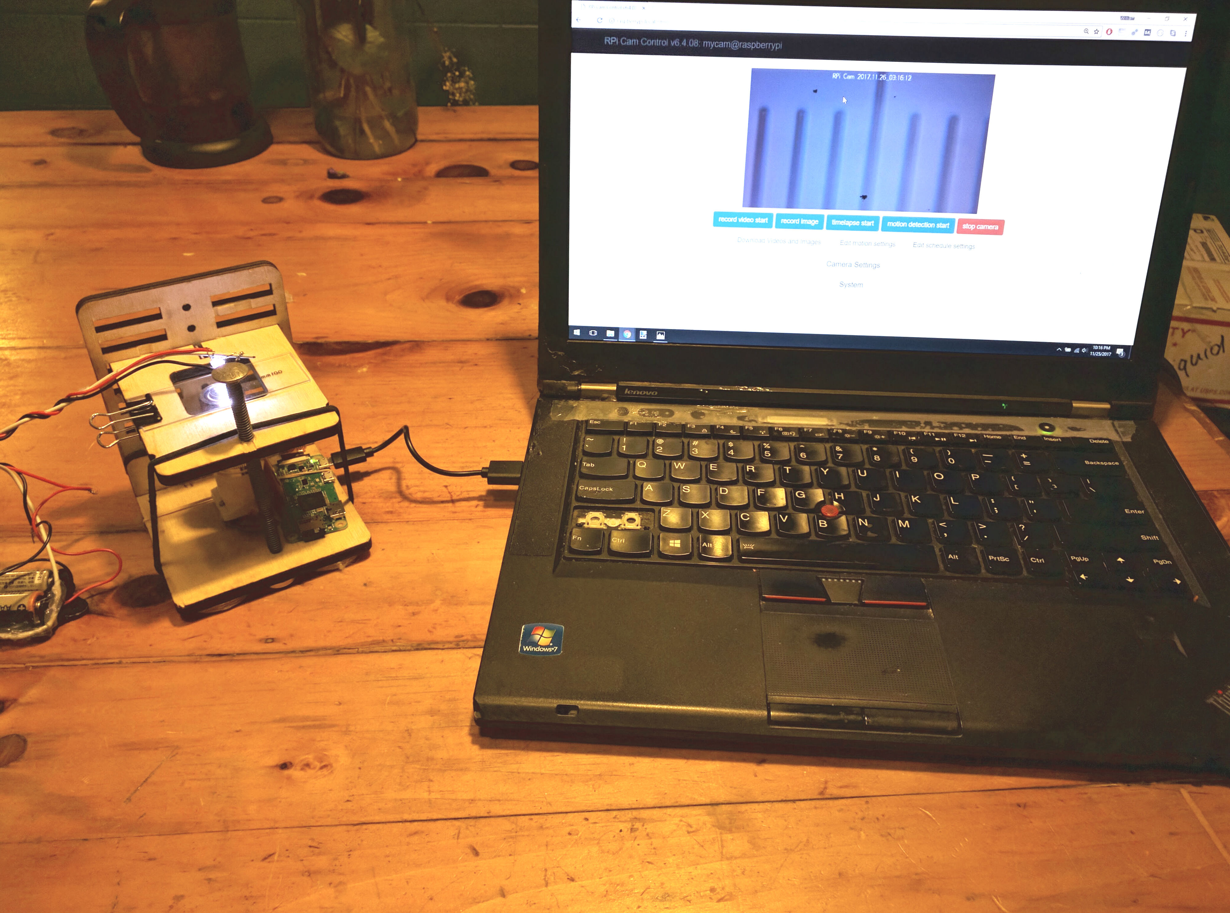
This setup is great, but if we're just trying to get images from a microscope, we don't need a standalone computer; we need a way to capture photos in real time. Instead we're going to set up the Raspberry Pi Zero for wireless streaming to send images from our camera directly to the computer.

We're essentially using the Raspberry Pi Zero as a web server to stream images from the Pi camera over the local network. This will let us access the images directly from any local computer by typing in a web address. It also makes our microscope significantly more portable.
We use the Pi Zero W because with proper configuration the built-in wifi allows us to do all of our communication with the camera over a network and avoid ever plugging a monitor and keyboard into the Pi directly.
Step 2: Attaching Your Raspberry Pi Camera to a Microscope Objective Lens
Full build instructions: Attaching Your Raspberry Pi Camera to a Microscope Objective Lens
A microscope objective is essentially a stacked lens that gathers and focuses light to magnify an image. We'll be working with 40x and 100x objectives that you would typically attach to a stereo microscope. Rather than a conventional eyepiece, we're using the sensor from a Raspberry Pi camera to capture and stream images directly to our laptop. The objective is connected to the sensor by a 3D printed optics tube.
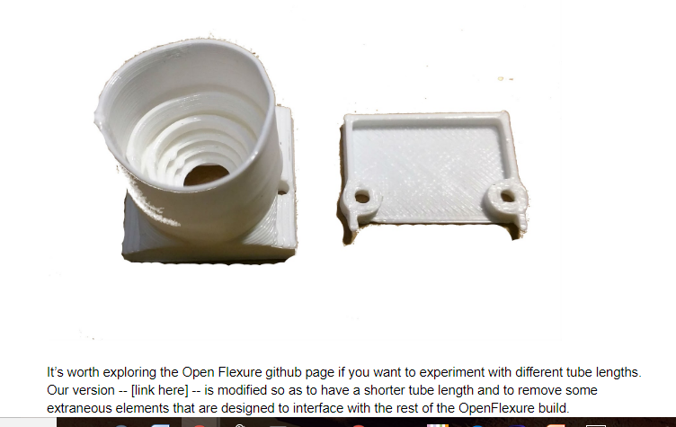
Adadpting the Open Flexure optics tube. We've been using parts developed for the OpenFlexure microscope project to connect our camera to our lens. While we found the assembly process for the entire OpenFlexure microscope to be more complex and difficult then we wanted for a first DIY microscope project, they have produced a lot of useful 3D models of parts to interface with the Raspberry Pi camera.


Step 3: Building the Microscope Stage
Full build instructions: Building the Microscope Stage
The goal is to make a stand that holds the camera mount and lens in place and allows you to place a sample just barely above the top of the objective lens with a system for moving the sample up and down very small amounts to bring it into focus. We use a laser-cut microscope stand based on a design made by the Hackteria -- https://hackteria.org/wiki/DIY_microscopy

Dimensions for 40 - 100x objective. The camera holder and tube and 100x objective lens are together about 73mm tall. The 40x objective that we're using is about 2mm shorter than the 100x, but the setup for both of them is roughly equivalent.
One of the reasons we've been using this design is because the Open SCAD files they provide are very easy to use and modify. https://www.thingiverse.com/thing:1057872/#files

The frame is put together so that the top of the objective lens is just slightly below the surface of the stage where you will place your sample.
Step 4: Attaching a light
Full build instructions: Lighting Your Sample
The important thing about the illumination is that it be a small, very bright point light source. We want all of our light to be going into a very narrow aperture at the top of the microscope objective lens. Almost any light source will do, as long as it is bright enough and we can easily point it into the lens.
We decided that the cheapest thing to do would be just to wire up a single bright LED to a power source and glue it to a piece of flexible wire. You could save yourself this step by finding an already existing suitable light source. Our build for this involves 2 AA batteries, a battery holder with a built-in switch, some extra wires, a length of coat-hanger wire and some hot glue. This is very far from the optimal way to build this, but it works.

Step 5: Testing and Calibrating Your Microscope
Full build instructions: Testing and Calibrating Your Microscope
To calibrate our microscope we will use a device called a stage micrometer. A stage micrometer is a tiny ruler mounted on a slide. Our ruler is 1 mm across and is divided into 100 ticks. The distance between each tick is 10 microns.

Step 6: What Can We See? Looking at Dust
More details here: Looking at Dust
This is the most current version of this microscope:
.jpg")
We looked at a couple of different samples with a 40x objective and a 100x objective to get a sense of the kinds of images we can produce with this setup. The first two are reference images; the third is a slide that (we were told) comes from a quarry near Wisconsin. Using the 100x objective, you can make out the shape and outline of dust particles in the 2-5 um range, which gets us a step closer to being able to identify respirable particles using this setup.


13 Comments
This looks amazing. You can embed an activities grid on your post using
[activities:raspberry-pi-microscope]or whatever tag name you want to use! Then there'll be a button to post activities.I'm especially interested in the one on setting up the Raspberry Pi as a WiFi camera -- it has additional applications on the Raspberry Pi Spectrometer and Raspberry Pi Timelapse and Raspberry Pi Infragram projects!
Awesome!
Reply to this comment...
Log in to comment
@stevie awards a barnstar to partsandcrafts for their awesome contribution!
Reply to this comment...
Log in to comment
This looks really nice! I'll start assembling the parts! in the mean time, a small suggestion: place a diffuser (piece of parchment paper) between the LED and slide to get more homogeneous illumination. I might be wrong about it, need to setup and play with it.
Reply to this comment...
Log in to comment
Hi, I would like to use the raspberry pi camera holder but the link is no longer posted. Can you please (re) post the stl files. Thank You
Reply to this comment...
Log in to comment
@MaggPi -- Sorry about that. I didn't update the link to the research note version of the instructions. I will do that now.
The correct links are posted on this research note: https://publiclab.org/notes/partsandcrafts/02-15-2018/2-attaching-your-raspberry-pi-camera-to-a-microscope-objective-lens -- I am copying them below as well.
http://partsandcrafts.org/pi_microscope/optics_modified_partsandcrafts.stl http://partsandcrafts.org/pi_microscope/picamera_2_cover_modified.stl http://partsandcrafts.org/pi_microscope/picam2_lens_gripper.stl http://partsandcrafts.org/pi_microscope/picam2_lens_remover.stl
Reply to this comment...
Log in to comment
Thanks! also thinking of using the picamera cover/holder for a spectrometer build BTW
Reply to this comment...
Log in to comment
This is just a note that my 3d print company flagged the design for the pi-camera holder , I don't think its a problem but I am not sure how to correct the stl file.....
Thank you for ordering with i.materialise. Unfortunately your order is currently on hold, because it looks like your design(s) needs to be adjusted before we can print it. In order to continue with the printing process, we would like you to take a look at the following issue(s):
New model.3mf (Polyamide (SLS)/Natural white): • extra surfaces with no thickness have to be eliminated.
• The walls of your model are not thick enough. This might cause fragile parts to break during printing. You can find the recommended minimum wall thickness for Polyamide (SLS) in our design guide or you can read our tutorial about choosing the right wall thickness.
https://i.materialise.com/blog/en/how-to-get-the-perfect-wall-thickness-when-turning-your-3d-model-into-a-3d-print/
https://i.materialise.com/en/3d-printing-materials/polyamide/design-guide#WallThickness
Reply to this comment...
Log in to comment
Oh, hmm. You may want to ask here: https://github.com/rwb27/openflexure_microscope/issues/
I also wonder if you could choose a different material or try ordering from another vendor?
Is this a question? Click here to post it to the Questions page.
Reply to this comment...
Log in to comment
I see the little triangles of zero-thickness. My slicer (Simplify3D) ignores them, so it looks like they will print okay. @MaggPi, would you like me to send you a couple of prints of those parts?
Chris
Is this a question? Click here to post it to the Questions page.
Reply to this comment...
Log in to comment
@Maggpi @Warren please consider deleting any message with personal details.
Reply to this comment...
Log in to comment
Hi, good call @amirberAgain - i wasn't sure if @MaggPi knew this was a public page, so I just deleted the comment. The rest of the comment was:
Reply to this comment...
Log in to comment
Sorry to detail here, you can get in touch via email if you like or repost your address if you want - I just wanted to be sure you didn't inadvertently share private info. Thanks! 👍
Reply to this comment...
Log in to comment
Whoops, I just noticed this. I will try to print the parts and let you know how it works. Sorry for the delay.
Reply to this comment...
Log in to comment
Login to comment.