This activity is a replication of This note.
Every five sample periods the MiniVol must be subjected to the routine maintenance of a cleaning, leak check, and single-point flow rate check.
Beyond routine maintenance, pump components may become worn, manifesting in irregular or erratic flow. Consult section 6.2 of the Manual to address these issues.
Maintenance Menu:
- Regular Cleaning
- Check for Leaks
- Single-point flow calibration
- Understanding Calibration
- Step-by-Step Calibration
Regular Cleaning
These instructions based on section 6.1.2 of the MiniVol TAS manual.
Every 5 sample periods or after checking that the Easy Maintenance Target inside the impactor is soiled.
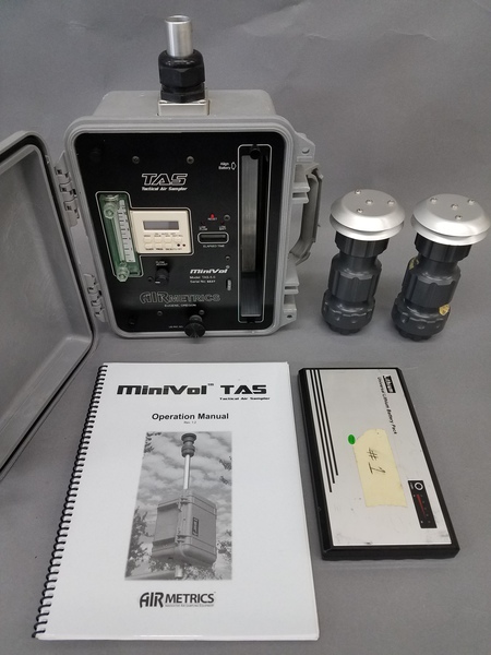
The MiniVol comes with two impactor assemblies with two EMTs each, one for PM10 and the other for PM2.5.

Opening up the impactor assembly:


Push the impactor out with your thumb:


The following procedure should be used for all four EMTs.
1) Clean the EMT by wiping with a clean lint-free cloth or paper towel. 2) Apply a small amount of low vapor pressure grease to the applicator. 3) Use the straight edge to apply the grease to the EMT in a spreading or "buttering" motion, so that it is a flat surface between the lip of the EMT.

4) After application wipe any excess grease from the edge of the EMT 5) Re-insert the EMT into the impactor.
Check for leaks
The pump need a quick check leak to make sure nothing was damaged in transit.
1) Remove the impactor/filter holder from the inlet tube, if its attached. 2) orient the MiniVol so it is vertical, with the inlet up top. 3) Unscrew the inlet tube compression fitting, pull the inlet tube all the way out, and tighten the compression fitting.

4) Turn the pump on by pressing the ON/AUTO/OFF button on the timer until a bar on the lower edge of the display is above "ON." The pump will start and the power indicator LED will light up.

5) Cover the air inlet tube with the palm of your hand.

6) The ball in rotameter (flow gauge) should drop to zero and should not be moving at all.

7) If the rotameter reads zero, turn the sampler off by pressing the ON/AUTO/OFF button on the timer until the bar on the lower edge of the display is above the "OFF." 8) If the rotameter does not read zero, proceed to "Troubleshooting leaks."
if the air inlet tube is covered the Low Flow LED will light up and the sampler will shut down after 15-20 seconds. Press the Reset button twice to turn the sampler back on.
MiniVol Calibration instructions
Understanding Calibration
Appendix A: Calculating flow rate, on page 59 of the MiniVol Manual describes this calibration procedure. Notes on the equations in the calibration can be found in this research question.
The MiniVol has a rotameter for setting and checking pump flow in the field. Its readings are only nominal, and not the exact 5lpm (liters per minute) that are actually needed. The MiniVol must therefore be subjected to a calibration once yearly.

The rotameter needs to be set for a number that corresponds to an actual flow rate of 5lpm (liters per minute), not an indication of 5lpm. To determine the actual flow rate, six measurements are taken with the flow calibration standard (in this case a MiniBuck) at six different flow rates from 4-6.5lpm as indicated on the rotameter.
These six points are then subjected to a linear regression, the results of which are used to calculate an a rotameter flow rate setting specific to the MiniVol that will achieve 5lpm under field conditions.
This calibration chart came with the MiniVol:

- mvol slope of the least square line from the linear regression
- bvol intercept of the least square line from the linear regression
- r2 coefficient of determination from linear regression
- Qind indicated flow rate on sampler's rotameter
- Qact actual flow rate as measured by the calibration standard
Q@std calculated flow rate at standard conditions, from Equation 1
standard pressure: 760mmHg, standard temp: 298°K)
Equation 1: Q@std = mvol x Qind + bvol
Qcalc calculated flow rate of sampler determined from the linear regression results
- Diff the % difference between measured and calculated flow rates
This chart and the calculations that are used to create it are withinthe MiniVol Spreadsheet, found here.
Step by Step calibration
Materials Needed:
- MiniBuck Calibrator
- MiniVol
- Charged MiniVol battery
- bubble level
- MiniVol spreadsheet
- Source for a nearby reading of atmospheric pressure
- calibrated thermometer for temperature
- Holder for faceplate

Before beginning:
- Identify a local source of weather information (see instructions in the activity and record the current pressure.
- Download the MiniVol Spreadsheet from here. It is in Open Document Format (ODF) and requires an ODF-compatible spreadsheet program such as LibreOffice.
- Prep a holder for the faceplate (cut a notch in a piece of wood, like this 2"x 4"


1) Prepare the MiniBuck Calibrator with the soap solution.

2) Insert the MiniVol battery.

3) Remove the MinVol faceplate to access the pump and internal plumbing. Remove the four faceplate thumbscrews and the sampler mount thumbscrew and lift off the faceplate.

4) At the back of the rotameter at its top outlet is a small brass orifice. Press the vinyl hose from the Minibuck over the orifice.

5) Attach the other end of the vinyl hose to the bottom nozzle of the MiniBuck.

6) Orient the MiniVol vertically, and balance the faceplate vertically inside the faceplate holder. 7) Check that the faceplate is truly vertical with the bubble level. It is crucial that the rotameter is truly vertical to get an accurate reading.

7) Take a reading of the temperature for the space you are in, and take a reading of the pressure from your local weather source. Record this information in the calibration spreadsheet.

8) Turn the pump on by pressing ON/AUTO/OFF button on the timer until a bar on the lower edge of the display is above "ON." The pump will start and the power indicator LED will light up.
Flow rate adjustment Warning: Do not turn off the sampler while adjusting the flow, and do not adjust flow while the sampler is off. When the two flow rate adjustment LEDs turn off, the sampler has recorded its flow rate and can then be turned off. Any error condition requires the reset button to be hit twice to reset.
9) Set the rotameter to 6.5lpm, reading from the center of the ball. This setting corresponds to the column Qind on the spreadsheet.

10) Turn on the MiniBuck. 11) Take a reading with the MiniBuck by pressing down the bubble wand. Record the reading in the column "Qact" on the spreadsheet, next to the Qind row with a value of 6.5.


12) Repeat steps 8-12 for rotameter settings of 6.0, 5.5, 5.0, 4.5, and 4.0lpm.
0 Comments
Login to comment.