A Coqui is a device that generates an audible output frequency that is a function of any resistance-based measurement. For example, a Coqui can measure:
- conductivity
- temperature
- ambient light
- LED light - particularly fun!
Coqui BBv1.0 is a version of the Coqui that is made on a breadboard, with just a few simple parts. Learn how to make one below!
NOTE: a new version of this tutorial can be found here.
Making your own Coqui
Ingredients
- Breadboard
- Batteries (greater than 1.5 V)
- a piezo speaker
- a capacitor (e.g 0.1 uF, 1 uF, or 10 uF)
- prototyping wires
- (pick one or several) -- a photoresistor; a potentiometer; a thermistor
Here's a digikey shopping cart with enough of the above ingredients (+ extras) for Coqui kits, at a cost of $19 per kit + shipping.
Schematic
The basic circuit for Coqui BBv1.0 is this:

The frequency of the output is a function both of the resistance, 'R' (which can be either a resistor, or some water between two electrodes, or a photoresistor, or a thermistor, or a potentiometer ... anything that will provide an electrical connection, with some resistance), and a capacitor, 'C'.
The frequency of output is given by: 0.7/(R*C).
Note -- the 555 chip is oriented in this picture such that the little 'circle' or 'divot' in the chip is oriented downwards. E.g., this chip (which has both a 'circle' and a 'divot') share the same orientation in this photo:

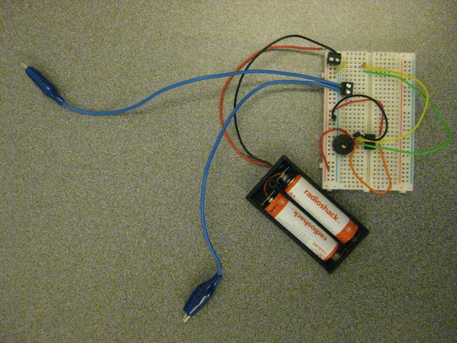
And this is what it looks like on the breadboard:

Quick notes:
- the green 'R' in the diagram is a resistor that tunes the frequency of the 555 output (which we'll be hearing via a speaker)
- the blue 'C' in the diagram is a capacitor. For low conductivity solutions, 0.1 uF is a good range to use. For higher conductivity solutions (like salt water), 1.0 uF, or even 10.0 uF, might be better values to use, in order to keep the output frequency in the audible range.
Below are the step-by-step instructions for assembling the circuit.
Step-by-Step instructions
Step 1: Pin # 4 to VCC

Step 2: Pin #8 to VCC


Step 4: Pin #3 --> speaker -
Here’s a picture of how the speaker is connected on the board:

Here’s what it looks like using the typical speaker from kit (which has the wires on the bottom):

Step 5: Pin # 3 to some row:

Step 6: Pin #2 to a row right below previous:

Step 7: Add a capacitor from previous pin to GND:

Step 8: Connect pin 1 to GND (sorry, no pic yet!)
Step 9: Using a photocell as a sensor: add the photocell between the previous two wires:
The photocell:

The circuit:

Step 10: Connect the battery (positive / red to VCC, negative / black to GND):

Step 11: Optional: place an LED between VCC and GND to make sure there’s power, when debugging:

Done!
Here’s a demo of playing with the photocell …
7 Comments
I've been waiting for the schematics of this to be released this for aaages...
It looks awesome!...when is public labs going to start selling them?
Is this a question? Click here to post it to the Questions page.
Reply to this comment...
Log in to comment
Hi, Amy! I think @donblair is busy deploying Riffles in Colombia, but @wmacfarl made an Upverter version of the circuit that's quite compact -- here: https://upverter.com/wmacfarl/ed1903e8ef25373b/Coqui----fixing-555-pinout/
I think you can order them online -- Will (wmacfarl) did and i have one. I think it needs to be tested out though - Will wasn't sure it was 100% correct.
I'm sure @donblair will have input and maybe a new version or something when he's back from his trip, but until then, this is what I'm aware of.
Reply to this comment...
Log in to comment
Since the two main ways to control the sound are the saltiness of the water and the size of the capacitor, it would be cool if this list of parts included some other sizes of capacitors in addition to the 10uF, like a 1 and a 2.2.
Other supplies needed to do the things shown in the video demos include:
Reply to this comment...
Log in to comment
Other people have commented elsewhere how "trimmers" (capacitors with adjustable capacitance) exist, which would be a useful way to "tune" the sound, in addition to swapping out capacitors.
There are also updated discussions elsewhere about measuring conductivity, adapting this circuit to get better accuracy. https://publiclab.org/tag/conductivity
Reply to this comment...
Log in to comment
@taramei check this out for your venus flytrap work in brackish water!!!!!
Reply to this comment...
Log in to comment
Here's a report back (including video!) from a workshop led by John Keefe in August 2015 http://johnkeefe.net/make-every-week-audible-water-sensor
Reply to this comment...
Log in to comment
Hi all! With help from @zengirl2, @asnow and @bronwen, we've posted a new Coqui activity with a smaller breadboard and flatter wiring here: https://publiclab.org/notes/warren/03-01-2019/build-a-sound-generating-coqui-conductivity-sensor
Reply to this comment...
Log in to comment
Login to comment.