What I want to do
Wrap my head around the ways in which several inexpensive commercial image capture / light sensor devices transform incoming light into useful data, and the degree to which we're able to manipulate image processing settings on these devices.
In particular, I'm interested to sort through whether the 'single pixel' sensors like those on Adafruit's RGB board and Luminosity board (linked to in my previous note about a microcontroller design that aimed to incorporate both of those sensors would be useful for somehow calibrating Infragram imagery.
After great discussions with Chris on the "plots-infrared" mailing list, in which he was helping us think through the ways in which the various devices we've been using and considering for infragram and plant health imagery, I felt like I needed a chart.
My attempt and results
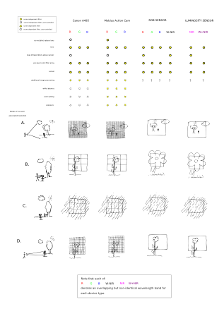
Here's the chart. It's not a great chart. I'm still muddling my way through thinking about this stuff:

The idea is to try to sort through what type of image processing (which I'm referring to generally as a 'filter' in the chart) is occurring when using each device. I made sense to me to break it down by a few characteristics:

- is the filter's behavior scene-dependent? I.e. does the in-camera software, or the user (or both) decide to change the filter's behavior on a shot-by-shot basis, or is the filter's behavior fixed?
- can the user control the behavior of the filter?
E.g., I'm thinking of the NIR-block filter that comes with a Canon Powershot as "scene-independent", and "user-controllable" -- if the filter is in place, then it has the same effect on incoming light, regardless of the scene; but on the Canon, the user can remove the filter.
The other aspect I was interested in thinking about was: what use might a "single-pixel" sensor be in calibrating an infragram camera? I tried to depict the various usage modes of these devices, and the resultant imagery (mostly thinking about resolution), in the bottom half of the chart:

For example:
If a Luminosity "single pixel" sensor were used alongside a Mobius when capturing a scene (say, holding the devices side by side, and aiming them both at a garden) could that somehow help to 'normalize' the Mobius camera's autoexposure process, which happens automatically, and isn't (is it?) under the user's control? This would be like using both the Mobius and the Luminosity sensors in mode "A" in the chart. It seems that this would require understanding the relationship between the results of capturing identical scenes (some LED tests?) using Mobius and Luminosity sensors.
What if an investigator were to first sidle up to a single plant in the garden, and hold up a Luminosity sensor directly in front of it (i.e., using the "Luminosity" column from line "B" in the chart); and then step back, and use a Mobius to capture the entire garden scene, including the plant (i.e. using the "Mobius" column from row "A" in the chart)? This seems like a lot of work, but could perhaps be useful when using e.g. a Mobius on a balloon to analyze crop imagery, and a Luminosity sensor to 'ground truth' the aerial imagery ...
Questions and next steps
I'd like to expand this chart with a visualization that compares the different wavelength sensitivity bands for the various devices being considered here.
Don't yet know how to fill in those questions marks in the chart ...
2 Comments
Things I want to know about your table:
I think that using the sensors to calibrate NDVI images from a camera requires sensor readings of just the light being reflected from a homogeneous area of plants. That area must be noted and later identified in the single-camera NIR/VIS photo. The NIR/VIS relationship from the sensors can then be used to adjust that area to get a similar NIR/VIS relationship. The same adjustment can be made to the rest of the image (unless you take sensor readings from multiple areas in the scene, but then why bother with the camera?).
Hooking up the sensors to the camera for synchronous collection is a long shot. It will be hard enough to make a device with the sensors that allows you to aim both sensors (probably through a felt-lined tube) at a homogeneous area of vegetation and record data with a timestamp or index number. Custom software will be needed to match up the photos with the sensor readings (unless there are just a few of each). Additional software will be needed to apply the correction to each photo (maybe a Fiji plugin). This will require manual intervention to identify the particular area of vegetation sensed by the sensor.
Using the sensors to calibrate Infragram photos is strangely similar to PeeBee's ideas in the comments to this note: http://publiclab.org/notes/cfastie/09-06-2013/mobius-stripped. I think PeeBee might be on to something, but my brain hurt trying to figure it out.
The Mobius Action Cam does not have a mode for triggering electronically. So triggering a Mobius and the sensor synchronously might not be possible. The Mobius does have a time-lapse mode, so it will shoot every 10 seconds and record a timestamp. That could be synced to the sensors doing the same thing. But that's awkward if the sensors have to be held close to the vegetation and the camera is farther away. The Mobius could always be triggered mechanically with an electronically controlled contraption.
Is this a question? Click here to post it to the Questions page.
Reply to this comment...
Log in to comment
Hi Chris,
Wow, so much good info / thinking here. Starting to dig into PeeBee's suggestions -- eager to see if I can make sense of them too -- he's very clear, but as you say, I need to wrap my head around his suggestions.
Ah -- here, I meant to refer to the Infragram filter, 'blue' or 'red-block' filter that folks have been adding on top of e.g. a modified Canon A495 with its internal NIR-block filter removed, in order to effect an 'Infragram conversion.' ...
Oh crap. You're right. It shouldn't be. Lemme fix that!
That's a good question, too. I was wondering how to think about that. I suppose what I'm trying to get at in this chart is how many 'manipulations' of the image data we're receiving using these various tools are a) occurring and b) within our control. So in that sense, I guess I shouldn't really apply a 'lens' row for the 'single pixel' sensors. I recall debating this, and then deciding that maybe I'd add it in case we might think about adding some sort of 'diffusion cap' above the sensors. But for now, I should wipe out those rows.
Ah, good question. In the case of the RGB sensor, it oughtn't, right? There's an NIR block filter above the entire sensor; but in the case of the Luminosity sensor, I forget now how that's set up. Let me find that description again ...
Ah, this recalls for me some earlier discussions about the various Infragram use-cases. I've gotten the impression (perhaps wrong) that when it comes to analyzing vegetation in this manner, the changes in leaf-by-leaf lighting conditions make it hard to assess whether individual plants are doing particular well, or not. But when one zooms out to the scale of, say, a large field of vegetation, then some of these variations average out a bit better, and you might be able to detect patterns -- e.g. that corner of the field looks like it needs more water. If several 'spot calibrations' with a ground-based, single-pixel sensor -- making measurements on several leaves at several locations in crops growing in a certain part of the field, and averaging them -- were then used to calibrate Infragram imagery taken from a balloon- or kite-based camera, perhaps this would make for a nice, calibrated system? Similar to how (I believe?) satellite imagery is calibrated by taking spectrometer readings on the ground?
Let me quickly fix the chart, and dig into your other ideas ...
Is this a question? Click here to post it to the Questions page.
Reply to this comment...
Log in to comment
Login to comment.