
Turbidity is an optical measurement of suspended solids in solution -- a broadly useful water quality parameter. Typical methods for measuring turbidity involve shining light into a solution, and measuring how much light either passes through the solution, or is scattered back at an angle.
While there are several 'gotchas' in turbidity measurements -- including the effect of temperature on typical LEDs and photodiodes, and differences in light scattering intensity and angle depending on the color and size of particles -- one very basic, immediate issue is: any changes in ambient lighting (e.g. sunlight, or light from electric lights in a room) can affect the light level measurements.
How to block ambient light? Mechanical methods are certainly possible, but they add significant complexity to enclosure designs. One wants water to flow freely past a light sensor (so that the sensor responds to sudden changes in turbidity), but wants the requisite opening to somehow also block light.
Are there non-mechanical means of reducing the impact of ambient light? Yes.
I'd recently been exposed to the concept of a phase locked loop, and, thinking it might be relevant to this issue of ambient light removal, did a little searching online.
I found one a particularly clear exposition of this concept -- relating it directly to photodiode measurements -- in Analog Devices' 'Technical Article MS-2624: Optimizing Precision Photodiode Sensor Circuit Design', by Luis Orozco -- which you can find it online, here; a local copy is here.
Frequency filters
The basic idea, here, revolves around the fact that, on the signal detection side of things, there exist fairly straightforward techniques for filtering measured signals in such a way that we remove any frequencies in the signal that are outside a specificed range.
For example, if we are only interested in frequencies higher than a certain frequency threshold, we can use what is called a high pass filter-- a filter (in an electronic circuit, this usually consists of a resistor and a capacitor) that dampens any frequencies below the threshold, and allows all frequencies higher than the threshold to "pass" through the filter and into our detection circuitry.
Correspondingly, if we were only interested in frequencies lower than a threshold, we'd use a low pass filter, which works in a similar way.
If we're only interested in frequencies that are within a certain narrow frequency band, we use a band pass filter.
There are lots of tutorials and explanations for how to build filter circuits for electronics. A nice exposition of building a band pass filter is here.
Here's a nice graphic illustrating the effect of a band pass filter on a signal (source):
The main thing to notice is here is that a band pass filter allows us to select a frequency range of interest, and ignore any other frequencies in our signal.
Modulating the emitter, filtering the detector
So, given that we can detect certain ranges of frequencies, how does this help us? Well, on the 'emitter' side -- the emitter being e.g. an LED that we're shining into our water sample -- we can simply e.g. switch our LED on and off at a particular frequency, $f$, and choose $f$ so that it is very different from frequencies associated with processes that we don't care about -- changes in ambient light due to day/night cycles ... shadows caused by clouds passing overhead (which might lead to light fluctuations of 1 Hz or less) ... or flickering due to electrical lighting (at e.g. 60 Hz).
That is -- by switching the LED emitter that is shining into the water on/off at some frequency t(1 kHz, say) that is different from the noise sources -- and then, on the other side, using a band pass filter so that we're only 'listening' for signal frequencies that are near 1 kHz -- we can effectively suppress interfering signals, and get an output from the measurement photodiode whose output correlates only with the the ~ 1 kHz light pulses coming out of the water, and suppressed all other frequencies. When the 1 kHz light pulses are sent through or scattered off the water, the amplitude of the measured pulses will still be enchanced or diminished by the presence or absence of particles in the water, so we'll still have our measure of turbidity; it's just that the input signal and the measurement signal will all be restricted to occur at 1 kHz, away from other interfering frequencies.
This is illustrated in Figure 9 from MS 2624:
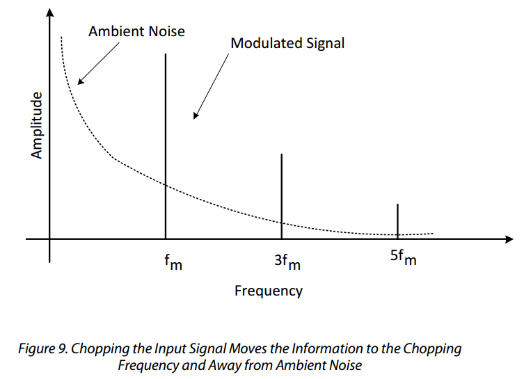
One subtlety in implementing this approach: if the modulating signal is a square wave (i.e., we simply turn the LED 'on' and 'off' at a certain rate), then the resultant frequency spectrum involves lots of harmonics -- multiples of the fundamental switching frequency. Some of these harmonics might have overlap with interfering frequencies that we wanted to avoid, and will make signal filtering more complicated. One solution to this is use a sinusoidal modulation signal (not too difficult); another solution is to pick a modulation frequency the harmonics of which don't overlap significantly with expected interference frequencies.
Note: these concepts are apparently quite related to how IR remote LEDs work. Most IR remotes seem to use a 'carrier frequency' of around 30 kHz, which is a frequency chosen to be sufficiently different from most natural sources of interference (ambient light) that a detector circuit tuned that frequency can ignore those other sources. It's also not apparently unrelated to how FM radio detector circuits work.
Synchronous detection
Here's another trick: because we are in control of modulating the signal, and because our detection circuitry for turbidity (a photodiode) is likely going to be physically proximate to our emitter circuitry (an LED), we can further reduce noise / unwanted signals by measuring our oscillating detector signal only at those times that it's in the 'on' state. I.e., if we're switching our LED on/off at 1 kHz, we can use the same on/off timing when measuring so that we only measure the voltage on our detector photodiode at 1 kHz, in sync with our emitter.
Another 'gotcha' emerges here: we need to be careful about any phase differences between our emitter frequency and what arrives at the detector. Because of reflections and other interactions, the 'peak' of our emitter frequency might not overlap precisely with 'peaks' at our detector. This can either be accounted for manually (by introducing timing delays in our synchronized measuremend) or through more sophisticated circuitry ('phase lock loop' circuits often have circuits that can shift the phase of detected signals to match the modulation clock frequency) or digital signal processing techniques.
Implementation
Of the techniques above, the easiest to implement quickly seems to be: modulating the emitter (LED) at a particular frequency (1 kHz, say), and then place a band-pass filter on the detection circuit (a photodiode) that is fairly tightly focused on the modulation frequency (1 kHz). The synchronous detection circuit would then not be very hard to implement as a next further step. The basic experiment might be: place the photodiode
References
Main reference article: http://www.analog.com/media/en/technical-documentation/technical-articles/Optimizing-Precision-Photodiode-Sensor-Circuit-Design-MS-2624.pdf
IR Leds: http://www.jensign.com/opto/ledmodulator/
FM: https://en.wikipedia.org/wiki/Frequency_modulation#Noise_reduction
6 Comments
Wow this is so well-written! Thanks for making these concepts accessible.
Reply to this comment...
Log in to comment
I need a little help understanding this background. When you modulate the LED at 1 kHz, that means it's flashing on and off 1000 times a second? How fast does the photodiode respond to stimuli with a measurable signal? Is the photodiode also looking for a signal occurring at the modulating frequency, and if so, how is the band-pass filter helping it do that? How is it producing false readings at harmonics of the modulating frequency with a square wave, but not a sine wave?
It seems like from a data and power saving standpoint, the first question would be, how small and how fast are the turbidity changes you need to measure? It might be easier to work around the timing overlap issue of the LED and the sensor, if both are shining and detecting for longer periods of time. You might get away with 1 measurement every tenth of a second or slower to capture all the data anyone could use, and still faster than any type of natural ambient noise cycles I can think of (unless your stream is near streetlights - then use 100 Hz?). If someone wanted higher modulation rates to deal with suspected noise, maybe that could be an adjustable parameter, down to the range in which the timing doesn't overlap well.
If you're interested in reproducability, you could do a 'burst' of 3 or 5 measurements (at 1kHz?) every 1 second -- that way, if you don't expect turbidity to be changing that quickly, you could report the average of those 5 values as the measurement, and the error from the standard deviation.
Could you help me understand how the band-pass filter would help on the detector? Is it just filtering out higher and lower light frequencies than what you'd expect from the LED, or does it change the timing somehow?
Even if you're flashing the LED at 1000 Hz, wouldn't you still see slow arcs in intensity, say, if the sun comes out from behind a cloud, and then goes back, overwhelming the photodiode so that the LED light signal was lost in the total noise light? Or would the benefit come during the data processing stage? You'd realize that your "sunny" values were no good.
Does the turbidity meter use the photodiode's reading of "base ambient light" for any calculations or data processing? And is it using the ratio of the transmitted light to the full emitted intensity to record values?
Wow, there are too many questions for you to answer all of them. It's clear I should read your posted reference material. :)
Is this a question? Click here to post it to the Questions page.
Reply to this comment...
Log in to comment
@pdhixenbaugh -- These are great ideas / questions / suggestions!
I just posted a quick follow-up here:
https://publiclab.org/notes/donblair/03-23-2016/sync-mod-for-ambient-background-removal-first-tests
Looking forward to digging into your questions in more depth soon ... I think (maybe!) some of them might be resolved with some upcoming experiments ...
Reply to this comment...
Log in to comment
Exactly.
That's a great question. I think the response of a typical photodiode is fast enough to handle 1 kHz. I should look into this in detail, but reasons to think so:
The better way to answer this question would be to dig up some specs online about the particular photodiode or phototransistor being used. Added this to my todo list :)
So, my (limited) understanding of this is: a typical band pass filter configuration allows you to specify a 'low' frequency level, f_L (below which any signal with a frequency less than f_L won't be seen) and a 'high' frequency level, f_H (above which any signal with a frequency greater than f_H won't be seen). One then places this filter circuitry between the photodiode (which is measuring the light pulses) and before the measurement circuitry (a microcontroller's analog input, say, or an oscilloscope), in order to implement this effect.
This is pretty nicely explained here -- much better than I could do, anyhow :) In particular, look at the figure titled "Animation of the additive synthesis of a square wave with an increasing number of harmonics".
Good questions. I'm imagining that we could measure the turbidity in a stream every 15 minutes, or even every hour, and probably capture the sort of information that we're interested in. Each measurement would then consist of this pulsed protocol -- pulse the LED at 1 kHz and measure the result -- maybe repeat that 5 or 10 times and average it.
Exactly -- the former -- we're exciting the water with light at a known frequency (e.g. 1 kHz) that is significantly higher than most of the interfering phenomena; measuring the light that is scattered back at us; and filtering this measurement so that we are only sensitive to light being pusled at around 1 kHz.
This is a great question. It may be that direct sunlight will still overwhelm a photodiode, so that it is not really registering the pulses. I may have witnessed something like this when testing with a lamp shining on the phototransistor up-close. Need to think about this more.
I was trying something like this before, and taking a base reading might still be a good idea, in the manner you describe. If we measure with the band pass filter in place, it would at least tell us whether our decision as to a frequency range that won't exhibit interference was a good one ...
Please do read the reference material, and explain it further to me! :)
Is this a question? Click here to post it to the Questions page.
Reply to this comment...
Log in to comment
I'll do what I can :D it might be good weekend reading. So take everything that follows from the perspective of me not knowing much about measuring turbidity...
If I'm understanding right, using the filter will help the detector record data only when the LED is shining - this is definitely useful!
Great! So this filters out (by averaging the signal?) any spikes or dips in light amplitude from, say, a fluorescent light flickering at 60 Hz. The signal at 60 Hz would be overwhelmed by the average of the signal at 1 kHz, since 60 mostly doesn't line up with 1000.
Question about two types of frequency: can the band-pass filter hone in on the electromagnetic frequency (and wavelength) that the LED is emitting and scattering back (helping to ignore ambient light), or is it getting a reading of all light, but at the modulation frequency?
If the data is still be affected by any type of slow interference out there, like sunlight and clouds, whose effect would be present during all bursts, how is that handled? Is the ambient-light reading, or opaque enclosure the only way to mitigate those? An enclosure might be something to avoid, if only to avoid having to maintain it frequently in the field, by cleaning out stream debris.
Last, are the accuracy and precision goals of this turbidity sensor still to measure and detect gross changes in turbidity, like from a pollution event, or to get turbidity readings that could be used by regulators or scientists?
Thanks :D
Is this a question? Click here to post it to the Questions page.
Reply to this comment...
Log in to comment
Re: square wave, I feel really out of my comfort zone here, but that's ok :). I know to make a square wave voltage source, you have to add up sine waves until you get something more or less square, but I haven't thought about going the other way - measuring on/off signals from the photocurrent of a photodiode.
If I'm imagining right, 1. the LED turns on, 2. the photodiode generates a voltage that ramps up and plateaus, 3. the LED turns off 4. the photodiode voltage decays rapidly down to ambient levels.
like this http://www.bme-bergmann.de/LR4_1MHz.gif (repeat 1000 times a second).
and we're just trying to measure the voltage value at the plateau. Do you still get harmonics in this scenario?
Is this a question? Click here to post it to the Questions page.
Reply to this comment...
Log in to comment
Login to comment.