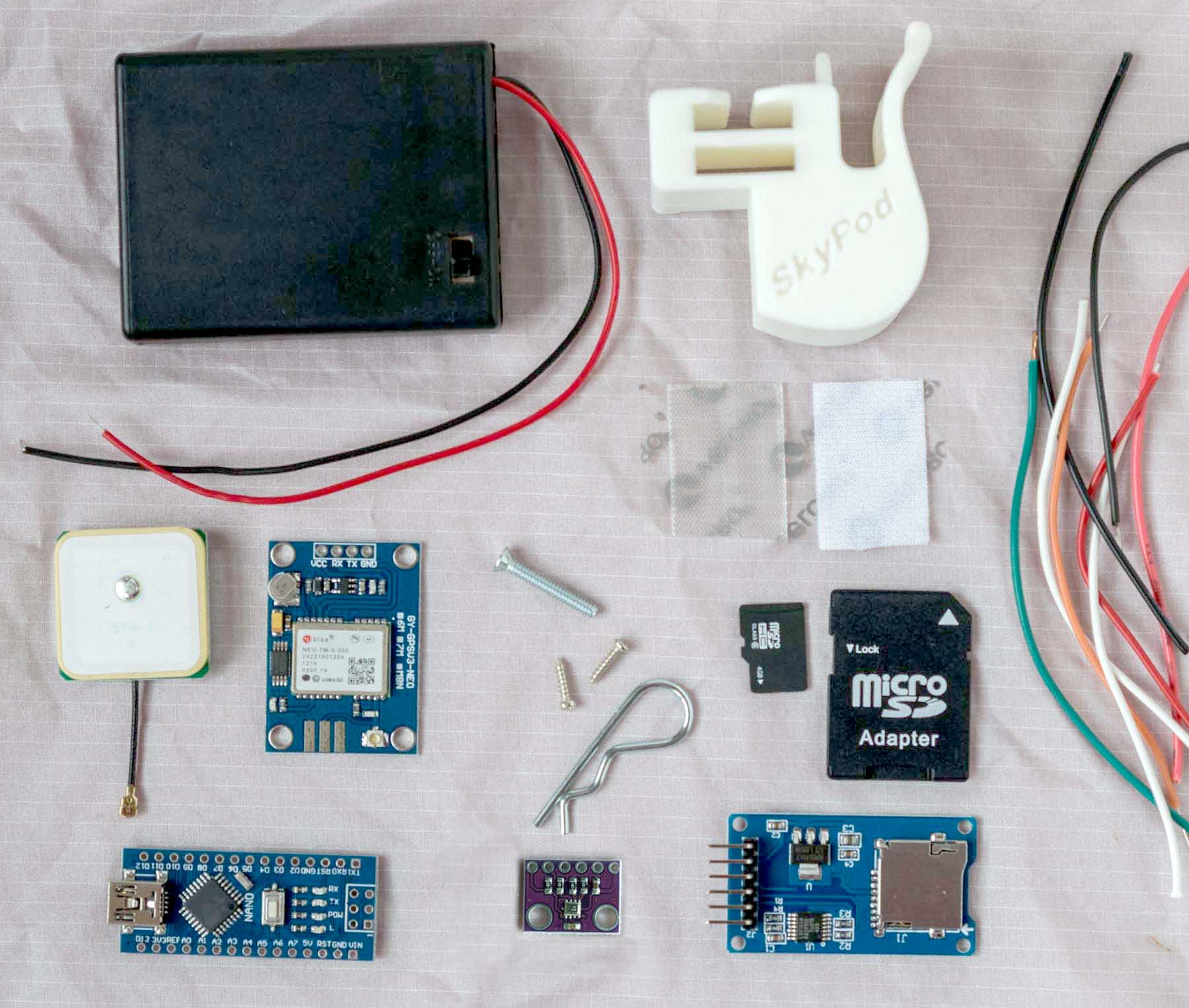
Above: A lot of soldering is required to assemble these parts into a data logger.
Assembling a SkyPod GPS Logger takes a few hours the first time you do it. I have assembled several of the current model plus a few early prototypes so I can do it much faster, although today it took about four hours to get one built and tested. More about that below.

Above: Sixteen wires connect the Arduino Nano to four other components. The first step is to solder these 16 wires to the Nano. They all go to the right to facilitate fitting everything into the 3D printed SkyPod bracket.
The SkyPod kit does not come with step by step assembly instructions. That would take away all the fun. Instead, the builder is presented with a conceptual plan:
Sixteen wires connect 11 pins (holes) on the Arduino Nano to 16 pins on four other components. A good circuit diagram is available. All the connections should be soldered. Just do it.

Above: This is not a dry fly. Four of the wires from the Nano have been soldered to the BMP280 sensor (lower left). Two of the other wires are longer than the rest -- these are the power and ground wires to the battery case. All of the wires have their free ends stripped and are ready to be soldered.
If all of the wires are 10 cm long, it will work well. I made them 9 cm long today, and it was a tight fit but a tidy result. The two wires to the battery case were longer, but they don't have to be. I stripped both ends of each wire first because that's easier to do before one end is connected to something, but if you're good at stripping, you can cut the length and strip as you solder to get the lengths just right.

Above: Two red wires (positive current) must be soldered to the same hole ("5V") on the Nano. If you are using a 5 volt sensor or other component, three wires must be soldered to that 5V pin. You can twist the three wires together and worry them through the hole (remove one of the tiny strands from each wire first to make it fit). A smarter way to solder three wires to one hole is to first solder them to a bent pin which can then be easily soldered into the hole. Four black ground wires must be soldered to the Nano, but there are two GND holes on the Nano, so only two have to go in each hole. The bend in the pin is important to keep the wires all headed "to the right" and to keep the Nano's profile low so it will fit into its narrow slot. After soldering, the end of the pin should be cut off near the other side of the PCB surface.

Above: This is what it looked like when I was finished with the soldering (or thought I was finished). The GPS antenna (upper left) snaps on.

Above: The microSD card board (right) comes with 90° headers already soldered on, so I soldered the wires to those. Heat shrink tubing covers the metal pins to prevent shorts. All of the other PCBs got wires soldered directly to the pin holes. The battery case got soldered wire to wire. The sensor (bottom) is connected to the 5v pin here, but the BMP280 sensor included in the kit must be connected to the 3v3 pin.

Above: When soldering is done, everything folds up and slides into the 3D printed bracket.

Above: The BMP280 sensor for barometric pressure and temperature is in the sensor pod (lower left).

Above: The BMP280 sensor needs some protection from wind, so I stuff a cotton ball into the opening and insert a piece of drinking straw to let some air in. There is also a hole into the sensor pod (lower left). Two straws might be better than one, it depends on how windy it is.

Above: Here is the vent hole into the sensor pod (lower middle). The primary function of this hole is for screwdriver access to the screw that will attach the SkyPod to the KAP rig. The Nano is visible through the larger, oval hole, with all the wires swept to the right.

Above: The 90° notch in the SkyPod bracket is where it sits on the shoulder of a KAP rig (or anything else with a corner). Two holes there allow screws to attach at right angles. The PCBs must be removed to insert a screwdriver to use these holes. The shiny cotter pin is inserted through pre-existing holes in both the GPS PCB and the microSD card PCB. That's all that holds them in place.

Above: The GPS antenna (upper left) plugs into the GPS PCB. A slot in the bracket allows the antenna cable to slide through. Adhesive Velcro holds the antenna on.

Above: From above. A single machine screw (top) prevents the Nano from lifting out. Note the narrow slot that the Nano fits in (top), and why all the wires are soldered so they can run in one direction. The green light (lower right) flashes when the GPS has a fix.

Above: The microSD card can be inserted and removed through the slot in the front of the bracket (center left). To program the Nano, connect a mini USB cable from your computer to the Nano (upper right).
I had everything soldered in about an hour today. When I loaded the sketch onto the Nano, nothing happened. I added some debugging code to the sketch and learned that the SD card was not being initialized. It took a while to figure out that I had reversed the MISO and MOSI wires. Don't know how I confused those acronyms. So I had to remove them, clean out the holes, resolder them, etc.
Back to the computer, and now the Nano was not recognized by the computer. How did I kill the Nano? Although I could not connect via USB to the computer, the power LEDs on the Nano and GPS board were on when I supplied battery power. I looked at the microSD card and it had new GPS data on it, so the logger was now working, and saving data to the SD card, but not connecting via USB. That was a new one for me. I examined the resoldered wires with a hand lens, but they looked good. I examined all the other connections and they looked good. I was stumped. I took a closer look at a capacitor on the Nano that I had noticed looked like it was poorly soldered. It was not near my soldering, but it was covered with solder. I poked at the capacitor with forceps and the solder fell off. I plugged in the USB cable and the computer recognized it. Everything worked fine. When I was resoldering those two wires, a tiny drop of molten solder fell on that tiny surface-mount capacitor and bridged it. The Nano still worked, but the USB port was disabled. It was sheer luck that I figured out what had happened. Arduino is the strangest universe I have ever played in.
Here are a few lines from the data file saved to the microSD card (Don't find the person who lives at that location and kill him or anything because I changed the numbers).
Sealevel BP: 29.92
Date,Time,Long,Lat,GPS_Alt,BMP_hPa,BMP_Temp,BMP_Alt
08/06/2017,20:20:56,-73.026354,43.917359,239.0,989.60,30.26,198.46
08/06/2017,20:21:02,-73.026339,43.917336,239.0,989.60,30.26,198.41
08/06/2017,20:21:08,-73.026324,43.917321,240.7,989.58,30.21,198.58
08/06/2017,20:21:20,-73.026339,43.917359,256.7,989.63,30.20,198.17
The first line is the sea level barometric pressure that the sketch used to convert barometric pressure to elevation. You should enter the current value in the sketch before you deploy the SkyPod.
The second line is the column headings (comma separated like the data below). So if you delete the first line and save the file with extension .csv, just double clicking the file will open it in Excel (default install on Windows). Excel will use the top line as headings and parse the data into columns. If you disdain using Excel, you probably know more about data files than I do, so deal with it.
The sketch for running the SkyPod is here. The SkyPod User Guide is here.
0 Comments
Login to comment.