Overview
The goal of this project was to make a reliable, quantitative turbidity sensor from easily accessible parts. The construction of the sensor involves a few pieces of PVC fittings that can be found at any hardware store, a 3D printed head to hold the optics in place, and an LED and photodarlington as the light source and detector.
Sensor Head
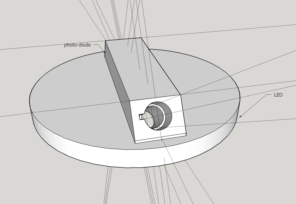
The sensor head is made from a 3D printed design. The head simply holds the LED light source and the detector (photodarlington) at a 90 degree angle from each other.


The LED and photodarlington detector are placed into their slots and epoxied into place. Once the LED and detector are in place, an acrylic window (0.118” thick, 2” diameter) is epoxied on to the front of the sensor head.


Wires are soldered on to the pins of the LED and detector. These wires will run to the signal amplifier board and micronctroller.
Once the wires are attached to the LED and detector, and the acrylic window is in place, then the sensor head is inserted into the end of a length of 2” PVC pipe (I used about a 4” length).The 3D printed head should fit snugly into the PVC pipe. The acrylic window has a slightly smaller diameter then the 3D printed head; this allows a ring of epoxy to be applied around the acrylic window to seal the head in place.


Since the sensor is sensitive to outside light sources, a shade cap was made from a 2” to 3” PVC adapter and an approximately four inch piece of 3” PVC pipe with some holes drilled in it. Although the picture does not show it, there is also a hole drilled in the slanted part of the 2” to 3” adapter. This hole is directly in line with the bottom edge of the sensor head when it’s inserted. This allows any air bubbles to escape.

Next a threaded end cap was attached to the back of the sensor. The wires from the detector and LED were run though a hole drilled in the end cap, which was then sealed with copious amounts of epoxy (sorry, no good pictures here).

Amplifier Circuit
I have not made a printed circuit board for the turbidity sensor yet, but the circuit I have been using on a bread board is shown below.

For turbidity solutions containing zero to one hundred NTU, I found that a two stage amplifier circuit worked best. I’m still playing with the circuit design so that different ranges of turbidity values can be accommodated. Updates should follow…
Acnoledgements
Thanks to Dr. Summers (WCU) and Brian Chee (UH) for the 3D printing.
15 Comments
Couple of questions: 1. Is the unit intended for submerged operation? 2. Extended deployment? 3. How is the water cycled to the chamber? 4. What are you using for calibration?
Is this a question? Click here to post it to the Questions page.
Reply to this comment...
Log in to comment
Hi ggallant. To answer your questions: 1. Yes, the unit is intended for submerged operation. So far I have only had it submerged in beakers in the lab, and I'm not sure what sort of depths the design will hold up too. It would probably mostly depend on the quality of epoxy used. 2. I hope to do some field test in the near future, but so far I have only tested it overnight in the lab without any problems. With extended deployments you would have issues of bio-fouling and instrument drift. The stability of the instrument seems good over the course of a few days, but I would probably want to check for drift at least once a week if I had it deployed in the field. 3. Since the instrument is designed to be submerged, the water is circulated by the movement of whatever body of water the instrument is in. Although a flow cell could be easily made from some PVC pieces and a water pump. 4. The lab I'm in has some turbidity standards that were ordered from Fisher Scientific. The response is pretty linear, so a two point calibration seems sufficient. I used a 100 NTU standard and distilled water for my calibration.
Reply to this comment...
Log in to comment
Hi @bhickman, this is great. Other folks (mostly @donblair) have been working on developing a turbidity sensor too. I have a couple of questions with your set up: (1) What wavelengths of light are you emitting and detecting? (2) Would the photodiode and amplifier you're using be compatible with the Riffle data logger? I'm not finding the latest research note on the Riffle, but maybe @donblair or @mathew could point you toward it or would know if it would be compatible. Thoughts? Also, what sort of price range is your LED and photodiode set? Thanks!
Is this a question? Click here to post it to the Questions page.
Reply to this comment...
Log in to comment
Hi gretchengehrke, thanks. To answer you questions: (1) I'm using this LED and this photodarling as the detector. The LED has a maximum output at 880 nm and the photodarlington has a maximum sensitivity at the same wavelength range. Currently the LED is $6.15 and the photodarlington is $6.45. (2) I'm not sure what the Riffle data logger is able to read, but the output of the sensor is a simple analog signal who's range can be adjusted by the amplifier board.
Reply to this comment...
Log in to comment
The LED is specified at 100ma. This "should" need a driver transistor. Outputs pins from the CPU are typically rated at 25ma max.
Reply to this comment...
Log in to comment
Hi ggallant. I'm using Texas Instrument's Tiva microcontroller which has a couple pins that allow you to tap into the bus power (5V at 1A). For short periods of operation I just continually power the LED from the bus pin, but for extended operations I do use a transistor and a digital I/O pin.
Reply to this comment...
Log in to comment
My current led and sensor boards are 6 sided and designed to attach to hardware store 3/4 plugs with plenty of epoxy and silicone sealant. Next rev will be bigger and will switch to using your LEDs and photo transistors. I have been using an h-bridge to drive the leds at 5V 100ma but will switch to transistor to keep the space down.
I have a small cap in the op amp feedback to dampen the photo diode response. Any comment?
Is this shape/size of interest to you?
Is this a question? Click here to post it to the Questions page.
Reply to this comment...
Log in to comment
Hi ggallant. Sounds interesting. I'm trying to picture your design, but I'm not sure if I have it right. Can you post a picture?
I definitely think a cap in the feedback loop is a good idea, and probably a cap on the power line as well. I'm still thinking about the best way to design the amplifier board to minimize power consumption and allow for a wide range of turbidity measurements.
Is this a question? Click here to post it to the Questions page.
Reply to this comment...
Log in to comment
I have decided to suspend my current turbidity sensor and instead adapt yours to my base station. If it is of interest I have modeled the mechanical parts in openscad and you are welcome to the files.
Also building a PCB to fit your chamber. Schematic is ready except for exact values of components (made a rough guess).
Some questions: I am unclear as the to location of the pipe with air bubble vents. Is the chamber with LED and PhotoTransistor wet? Is the 45 degree angle for LED and transistor important? Where did you get the black PCV parts?
Is this a question? Click here to post it to the Questions page.
Reply to this comment...
Log in to comment
Hi ggallant. I'm definitely interested in what you have put together. I'll check out openscad to see what you have.
As for the pipe and air bubble vent, I'll try and take some more pictures so its clearer whats going on. The chamber with the LED and phototransistor is supposed to stay dry. The initial idea was to put the amplifier board inside the chamber, but right now I have my amplifying circuit external to everything. Not sure which is better...
The 45 degree angle for the LED and phototransistor makes them 90 degrees from each other. I don't think having them exactly 90 degrees is essential, but you want to prevent the phototransistor from "seeing" the LED when there is nothing to reflect the light.
Reply to this comment...
Log in to comment
I parked the openscad design files at https://www.dropbox.com/sh/mzp8gketcuqufkq/AADkG_kmo2xcL3iWYOLi4YCxa?dl=0
If there is a better place, such as on a publiclab server please let me know. There is a png file showing the result. My riffle demo board arrived in the mail so my focus over the next few days will be on it. Let me know if you need help with openscad or modifying the files.
Is this a question? Click here to post it to the Questions page.
Reply to this comment...
Log in to comment
Hi ggallant. Your design files look great! I'm going to have to look into openscad. As far as a server, I don't think publiclab has one. I think most people use GitHub or Thingiverse for stuff like this.
Reply to this comment...
Log in to comment
Hi @bhickman and @ggallant! I was just reading this research note and comments again, and it sounds like such a promising project. Are there any updates? Great stuff!
Is this a question? Click here to post it to the Questions page.
Reply to this comment...
Log in to comment
Hi @gretchengehrke. I kinda let this project fall though the cracks. I did have the sensor working pretty well, the only issue was interference from stray light. Since then I have found this supplier of photodiodes with integrated optical filters (https://www.intorfilters.com/product-page/880-10-45). I think the optical filter on the detector would greatly improve the design. I have bought some supplies to make a similar sensor for chlorophyll with the optically filtered photodiode, just haven't gotten around to putting it together...
Reply to this comment...
Log in to comment
@bhikman, that integrated optical filter is neat, and surprisingly inexpensive! If you do pick this back up, I am super interested in seeing how well this could work. Smart design!
Reply to this comment...
Log in to comment
Login to comment.