Oil Testing Kit from a sheet of A4 Paper? (kind of...)
Sometime ago, @warren and @mathew were trying to make a container for the Oil Testing kit, from nothing but a piece of A4 paper.
This is what they came up with: http://publiclab.org/notes/warren/07-05-2014/oil-testing-spectrometry-workshop-at-fab-10
Since that time, I have been trying to develop a more efficient version. This is what I came up with so far.
It has a few minor issues/bugs, so I was hoping people here wouldn't mind giving their two cents on what can be done to make improvements.
The Lil' Box Itself.
This is what it looks like so far:

 (Ignore the hole in the top. That shouldn't be there)
How it works.
This image shows how the Box works; superimposed over the Public Labs Spectrometer.

What You Will Need.
-A Standard Sheet of 80GSM, A4 Paper. (I didn't have any black A4 paper so used what I had to absorb extra light in my current model)
-An Old Toilet Roll Tube.
-An Oil Testing Kit.
-Shiny/Reflective Foil.
-Tape/Glue/Paperclips.
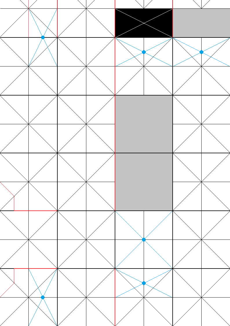
Step1: Folding.
Fold your sheet of A4 paper so that you have a grid of existing guidelines to use when the box is folded together.

Step2: Cutting.
Cleanly cut along the red lines (make sure your don't cut through the bit that attaches the lid to the rest of the box).

Punch holes through the dots at the center of the blue lines.

You should end up with something like this:

Step3: Sticking:
Stick shiny foil over the grey squares. The small flap should have shiny foil on both sides.

Also, stick the diffraction grating over the hole that is where the green dot is.

Step4: Assembling.
See the images here for information on assembling the box: https://plus.google.com/photos/108742728244628800104/albums/6064423192648884241?authkey=CJ-JiPXNkcWocQ
Spectral Workbench Test Images:
These are images that I have taken so far during the development process.
The latest of which uses my current model, which uses the curve of a toiler roll tube to deflect light towards the camera.
7 Comments
This is looking good. I love the grid layout pattern.
I see this is incomplete, but I wanted to let you know the black square (which has a slit cut into it) is not yet described in the text.
Additionally, there are six holes. It might help to specially mark the hole which needs diffraction grating in the diagram somehow. Maybe a differently colored dot? A rainbow dot? :)
I'd say there's nearly enough here for someone to put this together.
Is this a question? Click here to post it to the Questions page.
Reply to this comment...
Log in to comment
@btnoval
Thanks.
The black square is kind of ambiguous at the moment - I don't know what works best yet.
It has in the past been a horizontal slit, then a vertical slit and currently it is now a dot.
Also, in my current rendition of this, I have made it so that you can move the slit to be at any angle against the toilet roll tube.
This is supposed to act like focusing a lens on a camera.
Thanks for the advice on the diffraction grating. It is now marked with a green dot.
I would love to see/hear other people's attempts at this (if there are any)!
My old public labs spectrometer is bust so I am stuck using a super low definition camera & mobile phone cameras at the moment.
An issue I noticed with using a mobile phone is shielding out the light fully.
It was the reason that I put a lip around the hole for the camera, but even then, not all mobile phones have cameras in the same places.
My in-office solution to this is, stick a post-it note across the flap and then use that to shield your camera from outside light sources.
Also, it isn't specified in the instructions, but, you can cut the light rest to whatever shape best fits the light of your choice.
(I have a laser pen, but it isn't as bright as my Tech-Titan, which is huge and bulky).
Reply to this comment...
Log in to comment
are the turns in the light path for purposes of diffusion? It seems like I'm seeing a lot of stray light in the spectra.
Is this a question? Click here to post it to the Questions page.
Reply to this comment...
Log in to comment
@Matthew
More so convenience, but yeah, I am working in upgrading it so the slit. An be moved back & forth to allow more/less light through in the model using a loo roll.
Also, I was using black card around the insides to absorb most of the stray light.
Other than that, sorry, I'm not an expert in this field, so wouldnt know what else could be used other than that.
Thanks for your reply. Amy
Reply to this comment...
Log in to comment
*sorry for the spelling mistakes On a mobile phone.
Reply to this comment...
Log in to comment
The image under "How it works?" is beautiful. That's deserving of a poster or print.
Is this a question? Click here to post it to the Questions page.
Reply to this comment...
Log in to comment
@bsugar That is how it is supposed to work. I've realized a few teething issues and am going to do a writeup on it soon.
Reply to this comment...
Log in to comment
Login to comment.