My first use of image-sequencer https://publiclab.github.io/image-sequencer/examples/#steps= so I am not sure what to expect..
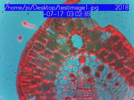
Image examples are microscopic images of plant cells. IR image was collected with a 850nm LED. Color image with a white light LED. I know NDVI is designed for remote sensing applications so I am not sure if this is worthwhile? Also not sure if microscope slide and cover glass changes image spectral properties?
First image is a Pine Leaf example. Is that the right image sequence for NDVI analysis?
Second image is of a leaf and has a flat field image problem. Can you add flat field correction to Image sequencer? I believe the supplied version of the Raspberry Pi camera has it’s own flat field correction and we need to provide an alternate correction when the Pi camera is used with a different (objective) lens.
Image sequencer works great (amazingly easy to use) but I am a little nervous as to it how it actually works. My experience with photoshop and opencv is that processing steps often depend on many decisions that depend on the situation.
10 Comments
Wow, this is really amazing! 🎉
Reply to this comment...
Log in to comment
@warren awards a barnstar to MaggPi for their awesome contribution!
Reply to this comment...
Log in to comment
@cfastie you might enjoy this one!
On Wed, Jul 18, 2018 at 5:16 AM \<notifications@publiclab.org> wrote:
Is this a question? Click here to post it to the Questions page.
Reply to this comment...
Log in to comment
Great job, @MaggPi....this is super cool!
Reply to this comment...
Log in to comment
I'm just presenting on your great post on the NASA AREN call right now (https://publiclab.org/aren) and we have questions!
Very cool! Folks on the call are excited about this test and would love to learn more!
Is this a question? Click here to post it to the Questions page.
Reply to this comment...
Log in to comment
We also just tried using different colormaps, with some success! Stretched:
And "fastie":
Reply to this comment...
Log in to comment
https://publiclab.github.io/image-sequencer/examples/#steps=ndvi{filter:blue},colormap{colormap:fastie}
Reply to this comment...
Log in to comment
MaggPi,
This approach is quite intriguing. You are correct that NDVI was invented and then used for 40 years primarily for high altitude aerial or satellite images (each pixel can include multiple square meters or hectares of ground surface). Producing NDVI images from low altitude (kite, balloon, drone) photography requires major changes in the way the NDVI images are interpreted (each pixel can include a small part of single leaf), and this fact is lost on some practitioners. Producing NDVI images from microscopic photos of plants requires even more modifications to how we interpret the results (only the pixels capturing chloroplasts might be relevant).
One important consideration is that the microscopic photography must be done on freshly prepared plant material. Is that a cross section of a living pine needle? NDVI depends on the way plant pigments absorb visible versus NIR light and that changes as the plant is stressed. Preparing the leaf sample for microscopy can cause stress, but it could take hours or a day for that stress to change the way light is absorbed by the pigments. So there is time to capture photos while the pigments are still behaving normally.
Traditionally, photos used for NDVI are captured while vegetation is illuminated by the sun and sky. Sunlight has a particular ratio of red:NIR wavelengths which is key to the production of NDVI images. NDVI is just a measure of the difference between how much of the red versus NIR in that sunlight is reflected from the vegetation. If the vegetation were illuminated by a giant LED, the NDVI result could be drastically different because the ratio of red:NIR in the LED might differ from that of sunlight.
In your example, you used different LEDs to make the visible and NIR photos (I assume you used the red channel in the RGB photo for your red data?). So there was some ratio of red:NIR in the light effectively illuminating your subjects, but we don't know how it compares to the ratio in sunlight.
Did you use a Pi NoIR camera to take both photos? If so, how much NIR was emitted by the white LED? And how much of that NIR was captured by the red channel in the sensor? These answers determine what wavelengths were captured by the channel you used to represent visible light.
Because you used two separate photos to make each NDVI image, the exposure of the photos could have altered the effective ratio. Healthy foliage reflects several times more NIR than red light. That is the difference that must be captured to make an NDVI image. If you make two photos of plant pigments, one of reflected red light and one of reflected NIR light, and both are well exposed photos, then there will be little difference between the brightness of the pigments in the two photos. The adjustments made to the exposure (brightness) of each photo will have made the brightness of both photos similar. Computing NDVI for each pixel with those two photos will have little meaning.
A potential workable approach could be to:
A remaining problem with this approach is that the camera sensor is not as sensitive to NIR light as it is to red light. So even if you control everything as described above, the values in the NIR photo will not be as large as they should be to represent how bright the NIR light reflected from the sample was. To adjust the result to compensate for that, you could use the sum of all three channels in the NIR photo or you could just multiply the NIR value in each pixel by a fudge factor (also called calibration constant). Or you could find a red filter which transmits only a portion of the span of red wavelengths (e.g., 640-660nm) and an NIR filter which transmits a wide range of NIR wavelengths (720-900nm).
With such a system, you should be able to capture microphotographs which produce NDVI images which show clearly where chloroplasts are. Or you can take a normal color photograph in which chloroplasts will be the only thing that is green.
Chris
Is this a question? Click here to post it to the Questions page.
Reply to this comment...
Log in to comment
Wow, thanks for the great response! I did this fairly quickly and I will try to catch up with the questions:
Here is reprocessed RGB split version. It’s not exactly the same as before since the IR is also split.
6b How much of that NIR was captured by the red channel in the sensor? Not certain
My initial thinking is that given the 100nm separation between the WHT / IR (850nm) LEDs and the high output; the amount of overlap would be difficult to notice.
Comment 1: Since the LED source approach doesn’t ratio the sun’s energy it seems inappropriate to call it an NDVI measurement. The approach, however, may be useful in a different context. 1) It exploits the key NDVI reflectance difference between vis and IR. 2) The basic equation (Image A –Image B)/(Image A + Image B) seems useful for general image enhancement even if the input isn’t spectrally pure for a valid NDVI result. 3) It’s very easy to implement (on/off LEDS) and could also be easily automated by the Raspberry Pi GPIO.
Comment 2. Does seem like a lot of wasted work since green chloroplasts are visible under white light. Is it possible other (non green but with IR )plant areas contribute to NDVI response?
Comment 3. It might be possible to mimic the Red/NIR ratio better with other LEDs. The likely candidates would be a red and IR (950nm) LED. This would increase the spectral separation and they are both low cost. See below for a red LED/ IR 850nm trial on a pine cross section.
Appreciate all the interest, comments and support.
Is this a question? Click here to post it to the Questions page.
Reply to this comment...
Log in to comment
Very interesting post! NDVI is correlated with chlorophyll pigments, correct? Different phytoplankton types have different concentrations of chlorophyll so NDVI could potentially be used to differentiate between types of phytoplankton. That could be used to inventory species in a specific body of water or it could potentially be used as an assessment of water health. There are certain species responsible for algal blooms (including toxic blooms) and if you could get a measure of their concentration in a sample you could monitor the growth over time leading up to an algal bloom. I’m not sure if any of this is feasible, but it’s an idea.
Is this a question? Click here to post it to the Questions page.
Reply to this comment...
Log in to comment
Login to comment.