This research note considers HDR imaging techniques for spectroscopy and microscope applications.
Introduction
Past efforts such as https://publiclab.org/notes/stoft/5-25-2013/hdr-search-high-er-dynamic-range and https://publiclab.org/notes/stoft/03-09-2014/hdr2-using-over-exposure-to-your-advantage have looked at High Dynamic Range (HDR) techniques for increasing the dynamic range of measurements. This note re-examines HDR spectral applications using current computer vision (OpenCV) algorithms and Raspberry Pi NoIR v2 controlled time exposures.
High Dynamic Range:
HDR has become a standard method to increase image dynamic range and is described in https://en.wikipedia.org/wiki/High-dynamic-range_imaging and https://docs.opencv.org/3.0-beta/doc/tutorials/photo/hdr_imaging/hdr_imaging.html.
HDR approach used for this research note consist of the following steps:
- 1)Four (8 bit/256) pictures are taken of the image scene. Exposure times are selected to cover a wide dynamic range that includes under and over exposed images.
- 2)OpenCV software is used to merge the four pictures into a single HDR file. Two algorithms are available (Robertson and Debevek) to merge the images. The HDR file maintains an effective 32 bit range and is stored in .hdr or RGB Exponent (RGBE) format (see https://en.wikipedia.org/wiki/RGBE_image_format.)
- 3)HDR pictures are tonemapped/converted to LDR (Low Dynamic Range)/ 8 bit images for viewing. Several processing options are used to display the HDR images: low/high scaling of Robertson/Debevek, Mertel Fusion and 32 bit contrast optimization (using Adobe Photoshop). Note that each of these tonemapping options have several adjustment parameters that can be used to further optimize the LDR image.
Spectral HDR Examples
Three spectral HDR imaging examples were observed:
-- Source/Grating/Camera
- White light LED/crossed grating/Raspberry PI NoIR camera
- CFL light bulb/crossed grating/ Raspberry PI NoIR camera
- CFL light bulb/linear grating/ Raspberry PI NoIR camera
The examples were selected to observe how saturation of the zero/first order impacts higher order spectra that have higher resolution. Slide image format (displayed left to right) consists of image collected with auto exposure, different timed exposures and processed tonemapped images.
White light LED/Crossed grating/Raspberry PI NoIR camera
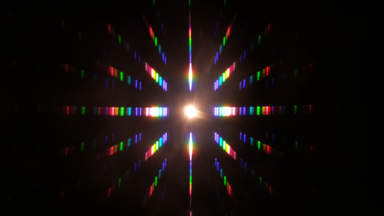
Crossed grating camera setup has been described in: https://publiclab.org/notes/MaggPi/07-09-2018/computer-vision-color-detection. This setup observes the 0, /- 1, /-2 and multiple sub orders in horizontal and vertical directions. The HDR processed images permit viewing all orders including orders saturated during long exposure times.
CFL light bulb/crossed grating/ Raspberry PI NoIR camera.
The picture below uses the same crossed grating setup but with a CFL light bulb. In this example, the HDR processed images permit viewing additional orders than cannot be observed in the initial timed exposures.
--CFL light bulb/linear grating/ Raspberry PI NoIR camera
Linear grating camera setup has been described in https://publiclab.org/notes/MaggPi/06-17-2018/how-can-you-use-computer-vision-to-reduce-spectral-overlap. This setup observes the first, second and third orders of a CFL light bulb. In this example, both the longer timed exposures and the HDR images permit a good view of the second order.
Microscope example: Unlike the above HDR spectral example, the microscope example illustrates an imaging condition where there are no saturated pixels. The image is of human blood cells observed with a 20x microscope objective/Raspberry PI camera/ white LED light illumination. Set up is described at: https://publiclab.org/questions/aquiles/07-13-2018/which-objectives-do-you-use The picture below shows the different HDR tonemapped images. In this example, HDR images seem to provide picture quality similar to the image collected with auto exposure settings.
Next steps: The different examples show how HDR processing permits imaging over a wide dynamic range. The next step is to determine if line spectra (vs an image) can be collected direct from the 32bit RGBE file and be used for spectral analysis. If anyone is familiar with mapping RGBE intensity profiles please provide comments.
Software code posted at: https://github.com/MargaretAN9. Python/OpenCV software (https://opencv.org/ ) used for HDR processing consists of two separate programs. The first program, takeHDRpictures.py, collects four (or more) pictures and saves the images and exposure times. The second program, HDRimaging.py, loads the images/exposure time data and creates the RGBE file/tonemapped images.
0 Comments
Login to comment.