Research question
Microscope calibration overlays... What's the best approach?
Introduction:
DIY microscope kits such as https://www.kickstarter.com/projects/publiclab/the-community-microscope-kit , seek to develop tools that are 'affordable and simple as possible while still providing great microscopic images'. One option to simplify microscopic measurement is to create overlays that provide a scale reference.
Microscope calibration procedures typically use a very small ruler of a known length that will permit an accurate comparison for additional measurements. For example:
https://publiclab.org/notes/mathew/08-23-2016/calibrating-a-microscope
https://publiclab.org/notes/partsandcrafts/02-26-2018/5-testing-and-calibrating-your-microscope
Using computer vision techniques it is possible to measure the ruler and display calibration references directly on a video display. The advantages of video overlay is that the viewer can see a reference scale and image at the same time.
Overlay Example
To demonstrate how a reference overlay could be used to assist microscopic measurements, computer vision software (opencv) was used to measure a calibrated ruler and then display a grid pattern.
A video run thru is at: https://youtu.be/fnmG-ueE_3k. (Best viewed at full screen to see the screen overlay.)
Step 1
A known reference is imaged and stored.
Step 2. A computer program reads the image and prompts the user to input scale information from the reference image. The software automatically computes a scale ratio which is used to create a grid overlay. (Note that the microscopic objective and camera resolution cannot be changed from step 1.)
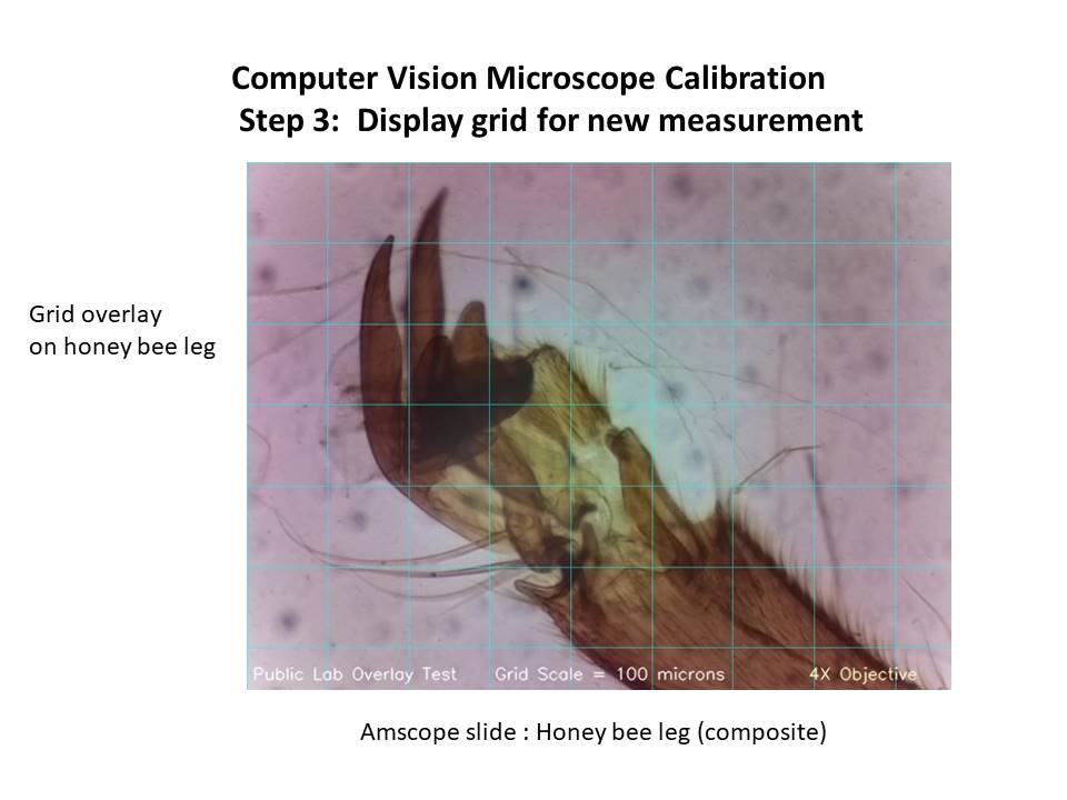
Step 3. New object is now inserted on the microscope stage and is compared with the grid overlay. The user can now easily scale the image as well as determine the total measurement area.
Note that the grid is square on the video display but rectangular when the image is converted to jpg format. The jpg grid measurement scale is consistent with the image scale.
This slide below demonstrates different type of overlay patterns.
Since there is wide range of techniques and display option available, this note request advice on best possible design and calibration methods.
-What is the best way to measure the reference and pass the data to the computer generated overlay? -What type of overlay should be generated? Color? Pattern? Live video or stored on image? -Should a grid be used at all? Would it be better to just generate a scale and insert on the image?
Note that I could also use computer vision to count the number of ruler divisions automatically. I didn't want to program this step until other calibration reference options were considered.
The goal is to calibrate without the cost of a purchased reference.
See: https://publiclab.org/notes/amirberAgain/05-23-2018/use-of-a-5-bill-for-microscope-calibration
The picture below attempts to use the side markings of a 5 dollar bill as a calibration reference. The irregular shapes would probably prevent any accurate measurements.
Related posts: https://publiclab.org/notes/amirberAgain/01-12-2018/python-and-opencv-to-analyze-microscope-slide-images-of-airborne-particleshttps://publiclab.org/notes/MaggPi/06-05-2018/usb-webcam-vs-raspberry-pi-v2-field-of-view-fov-comparison-community-microscope-initial-evaluation-2 Software posted at: https://github.com/MargaretAN9/Peggy/blob/master/Pi Camera/videooverlayfinal.py
4 Comments
I LOVE this!!!! Fantastic!!! ⚡⚡
Reply to this comment...
Log in to comment
Just starting to make some steps towards integrating this into the infragram video feed, where we can test it out. https://github.com/publiclab/infragram/issues/14
This is now working on Infragram's online demo at https://publiclab.github.io/infragram/ -- give it a try!
It'll work now on webcam microscopes, and as soon as #pi-builder rebuilds in https://github.com/publiclab/pi-builder/pull/53, we'll have that feature on all our pi-based kits.
Is this a question? Click here to post it to the Questions page.
This is cool, one possible approach would be to add preset points along the slider matched to different configurations of the microscope kits(settings for the different array/lens combinations). This would assume there isn't that much variation between kits since they have the same lens to object distance. In order to do this we have to take calibration pictures for each configuration and then create slider reference points.
This could also be done in image sequencer using overlay and grid modules.
So is this approach reasonable or is a calibration transfer (the method described in the front part of this post) always considered necessary?
Is this a question? Click here to post it to the Questions page.
Reply to this comment...
Log in to comment
Login to comment.