What I want to do
The plan here was to come up with something that would log water levels as the storm surge from a hurricane passes over a barrier island. The project was begun as a collaboration with the center for the study of developed shorelines here at WCU.
My attempt and results
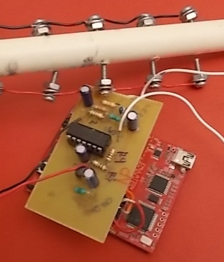
Most of the early work was done in Summer 2013 by Ms. Alicia Fowler and me. The main image shows our original design which used a pdip amp and through hole components. The system was built on a TI MSP430 launchpad development board with a g2553 microcontroller chip. Revision 1.5 of the launchpad (the current one) comes with this chip installed and can be purchased from TI for $10 USD (https://estore.ti.com/MSP-EXP430G2-MSP430-LaunchPad-Value-Line-Development-kit-P2031.aspx). The Launchpad is coded using the Energia IDE, download for free from energia.nu. The instrument requires an analog amplifier board that clips to the LaunchPad via headers. The schematic is presented below with the layout of a more recent surface mount board below that.

 The numbers on the schematic are all bogus. The quad op amp has to run off of 3.3 volts to ground, but other specs should not be critical. Values for the resisters and capacitors in the schematic should not be trusted. Anyway, in the surface mount version, a reference voltage (1.65 volts = vcc/2) is output as a pwm signal on pin 2.4 and fed to the non-inverting pins on three of the four amps of the quad op amp. The fourth amp is not used (the third is probably not necessary but I have a lot of quad amps making it cheaper than the shipping charges needed to get a dual amp). The reference is input on the upper left of the schematic. R8 and C5 are used to filter out the high frequency pwm signal, leaving an analog signal. The sizes of R8 and C5 need to be large enough to quiet the pwm. The faster your pwm, the smaller R8 and C5 can be.
Below the reference input on the schematic is the signal input, which connects to R1. The signal is a digital High / Low signal, so R2 and C1 are probably not needed. The hole pads at CE and WE are for wires that connect to the electrodes. As shown in the main image, we planned to use bolts strung together with wires as electrodes. As the water level increased, the number of bolts submerged would increase, and the current would increase. Anyway, the voltage across the two electrodes would be (Vref - Vsignal)(R3/(R1+R2)). By keeping Vref at VCC/2 and outputting a square wave over Vsignal (High, delay, Low, delay), a square wave with a period of 2delay and amplitude of 2VCC(R4/(R1+R2)) is established. Using values of R1= 6K, R2 = 600, R3 = 100, and VCC = 3.3 volts will give a 100 mV amplitude. Increasing R1 or R2, or decreasing R3 will make the amplitude smaller.
The numbers on the schematic are all bogus. The quad op amp has to run off of 3.3 volts to ground, but other specs should not be critical. Values for the resisters and capacitors in the schematic should not be trusted. Anyway, in the surface mount version, a reference voltage (1.65 volts = vcc/2) is output as a pwm signal on pin 2.4 and fed to the non-inverting pins on three of the four amps of the quad op amp. The fourth amp is not used (the third is probably not necessary but I have a lot of quad amps making it cheaper than the shipping charges needed to get a dual amp). The reference is input on the upper left of the schematic. R8 and C5 are used to filter out the high frequency pwm signal, leaving an analog signal. The sizes of R8 and C5 need to be large enough to quiet the pwm. The faster your pwm, the smaller R8 and C5 can be.
Below the reference input on the schematic is the signal input, which connects to R1. The signal is a digital High / Low signal, so R2 and C1 are probably not needed. The hole pads at CE and WE are for wires that connect to the electrodes. As shown in the main image, we planned to use bolts strung together with wires as electrodes. As the water level increased, the number of bolts submerged would increase, and the current would increase. Anyway, the voltage across the two electrodes would be (Vref - Vsignal)(R3/(R1+R2)). By keeping Vref at VCC/2 and outputting a square wave over Vsignal (High, delay, Low, delay), a square wave with a period of 2delay and amplitude of 2VCC(R4/(R1+R2)) is established. Using values of R1= 6K, R2 = 600, R3 = 100, and VCC = 3.3 volts will give a 100 mV amplitude. Increasing R1 or R2, or decreasing R3 will make the amplitude smaller.
The voltage at the current read pin should be Vref + R4R6/R5(i), where i is the current passing though the electrode WE. We read the voltage at the end of the high pulse, then go low and read again. Since the current at the end of the low pulse (i-Low) should be -(i-High), taking the difference between the two read values subtracts out Vref and doubles the signal (I may have the sign wrong on this. If I do, you will need to subtract the high reading from the low and sum).
The code goes something like below (ignore the periods in the first three lines, I had to put something there or else the research note formatting got messed up):
///////// conductivity meter code ////// ///// Jack Summers, written on the fly, Nov 21, 2013 /////
. #define Signal_pin P2_1 // output square wave on P2.1 . #define iRead_pin A3 // read current on A3 . #define ref_pin P2_4 // ref output to amp non-inverting from P2.1 int d1 = 1; // delay = 1 ms gives 500 Hz freq unsigned long value; //current read
void setup() {
pinMode (Signal_pin,OUTPUT); // set pin 2.1 for output
pinMode (ref_pin,OUTPUT); // set pulse pin as output
pinMode (iRead_pin,INPUT);
analogResolution(255); // divide the full duty cycle into 255 steps
analogFrequency(5000); // set the full duty cycle to 0.2 ms
Serial.begin(9600); // begin serial comm. at 9600 baud
analogWrite(ref_pin, 128); }
void loop() { value = 0; for(int i=0; i<16; ++i) { digitalWrite(Signal_pin, HIGH); delay(d1); value += analogRead(iRead_pin); // read high with positive current digitalWrite(Signal_pin, LOW); delay(d1); value -= analogRead(iRead_pin); // read low with negative current } Serial.println(value); }
notice that we are summing sixteen iterations of the difference between the current read at the high and low pulse, then send the value to the serial com port.
Questions and next steps
I don't remember what the frequency we sampled at was and I don't remember what the resistor values we used. This worked fine for a few hours, but over the course of a few days, we had corrosion problems in our tests. We originally used normal machine screws and we need to look at stainless steel. The current should increase, roughly exponentially with decreasing delay time. We did not investigate that. We also did not put any effort into logging the data. There is an SD card shield available for the LaunchPad (http://store.43oh.com/index.php?route=product/product&product_id=70) and I believe that Ben H. has written code to log data to it. We have plans to make a Raspberry Pi version of this, but ... That is all for now. Let me know if you have questions. Jack
2 Comments
hi jack! if you put four spaces or a "`" (reverse quote) at the start of a line it will allow you to post code snippets.
function demo() {}like that
Reply to this comment...
Log in to comment
er, with the quotes you have to surround the code with them.
Reply to this comment...
Log in to comment
Login to comment.