Disclaimer:
This research note was begun in April, 2014 to allow data logging using commercially available probes sold by Vernier Instruments. The design did not turn out to be compatible with Vernier pH probes or ion selective electrodes. A newer design that does work with these probes is available here. At the time I wrote this note, I did not have a firm working understanding of how Vernier probes interacted with their recording devices and I assumed the probes were passive devices requiring amplification to get good precision. In fact, the probes in question have amplifiers built in and these need to be powered and do not require amplification.
What I want to do
Our goal is to provide an open source data logger for use in education and environmental monitoring. While there are commercially available data loggers (such as those from Vernier and National Instruments), we believe that having an open source product will keep costs lower and will ultimately allow greater flexibility in what can be measured.
Background:
In a previous research note (found here), I describe writing software for logging data to a computer using a Texas Instruments MSP430g LaunchPad development board. The LaunchPad code was written using the Arduino-like language, Energia and the GUI was written using Processing. The early code is available from our GitHub page, here.
My attempt and results
One of the big impediments to making a data logger is to have access to a large variety of sensors and probes. This report describes our effort to get around this by making something that will interface with the probes that are available from Vernier Instruments (web site here). Vernier sells a wide variety of probes that connect to their data loggers via British Telecommunications plugs. There are two types; the BTA (analog) and BTD (digital) plugs. Both plugs have recently become available from Sparkfun. We have designed a two channel data logger to accept and amplify signals from low voltage sensors, such as pH electrodes, ORP sensors, thermocouples, etc. A simplified schematic for one channel is presented below:

In this schematic, an offset voltage (Voff) is provided by the pin labeled PWM, and the amplified voltage difference between the two inputs is read at the pin labeled READ. The purpose of the offset voltage is to allow measurement of negative voltage differences. The read voltage is determined by the Voff, and the resistances of R1 and the potentiometer (Rpot):
Vread = Voff + R1/Rpot (input+ - input-)
Since the theoretical voltage difference for a pH electrode will be ~59 mV per pH unit, a 12 pH unit range will cover 700 mV. Since the dynamic range of our microcontroller is 3.3 volts, we will want to be able to amplify by a factor of ~5. That means that a 10 Kohm potentiometer and R1 of ~2 Kohms should work.
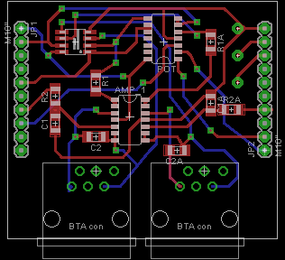
The main image for this note is the board file created in Eagle for measuring amplified signals from two probes connected using BTA connectors. Since each channel requires three amps, we use one quad and one dual op amp. The design also incorporates a digital potentiometer, which we will control from the GUI. A bill of materials with sources, part numbers and estimated costs (USD) is provided below:
Tiva Launchpad     Texas Inst   EK-TM4C123GXL   $12.99
BTA connectors (2)   Sparkfun    PRT-12753            $3.90
quad op amp       Digikey    MCP6004-I/SL    $0.53
dual op amp         Digikey  LMV358IDR       $0.82
digital pot       Digikey   MCP4231-103E/SL  $1.08
The design also requires a few resistors, capacitors, and 1 x 10 socket headers.
Questions and next steps
I have ordered three copies of the printed circuit board from OSH Park and a solder stencil from OSH Stencils. Once the boards come in, I will assemble them and try them out. If the boards work as expected, I will transfer the design to the "shared projects" at OSH Park, making the boards available to anyone willing to pay $18 for three. The software for the microcontroller and GUI need to be re-written and transferred to the GitHub page.
Why I'm interested
The dogs tell me that the barking in my head will not stop until this project is finished, written up, and on line.
2 Comments
Ah, this will be a great thing! Leveraging the widely-available Vernier probes with open hardware will be a fantastic advance. Would it be possible / easy / sufficiently inexpensive to add the appropriate connector for BNC probes as well?
(And good with the barking :) I've got so much barking I'm hoping to quell by finally writing up the research note backlog ...)
Is this a question? Click here to post it to the Questions page.
Reply to this comment...
Log in to comment
Sure, BNC connectors just connect to two pins. It would be fairly trivial to exchange one or both BTA connectors with BNC connectors. It would mean making an Eagle footprint for the connector you want to use, but the Sparkfun tutorial on this is pretty good (https://learn.sparkfun.com/tutorials/designing-pcbs-smd-footprints). I would use a connector that mounts on the board. If I were willing to make my own probes, I would start with phone or ethernet jacks because you can buy the stuff at Lowes. Bad news about the barking: the dogs tell me that I need to get the code on GitHub as well. Jack
Reply to this comment...
Log in to comment
Login to comment.