Introduction
These instructions will guide you through the assembly process of the desktop spectrometer. This guide is an activity and you can check the activity grid for spectrometry to find what you'll want to do next, which is calibrate your spectrometer
If you would like to print these instructions, download the pdf file here
This kit must be handled and stored carefully, as rough treatment can affect calibration by >6nm -- consider keeping it in a sturdy box like the one it came in, or upgrading it to increase stability . (Read on!)
If you have found any way to improve this kit for any specific usage, share it!
As an example, Public Lab user stoft has made an adjustment to improve the stability of the desktop spectrometer, something that may be important when analyzing fluorescent materials and for many other usages. Please try out this upgrade and others that can be found in our upgrades grid
You can also post your own, new upgrade for people to try and if you have an idea or a need, but aren't sure how to solve it yourself, you can request an upgrade here
Have a question?
If you have a question about spectrometry, submit your specific queries at publiclab.org/questions and try to use relevant tags (like spectrometry among others) to make sure that people find it.
If you have a customer service, shipping, ordering, bulk ordering, sales, or business related query please send an E-mail to kits@publiclab.org
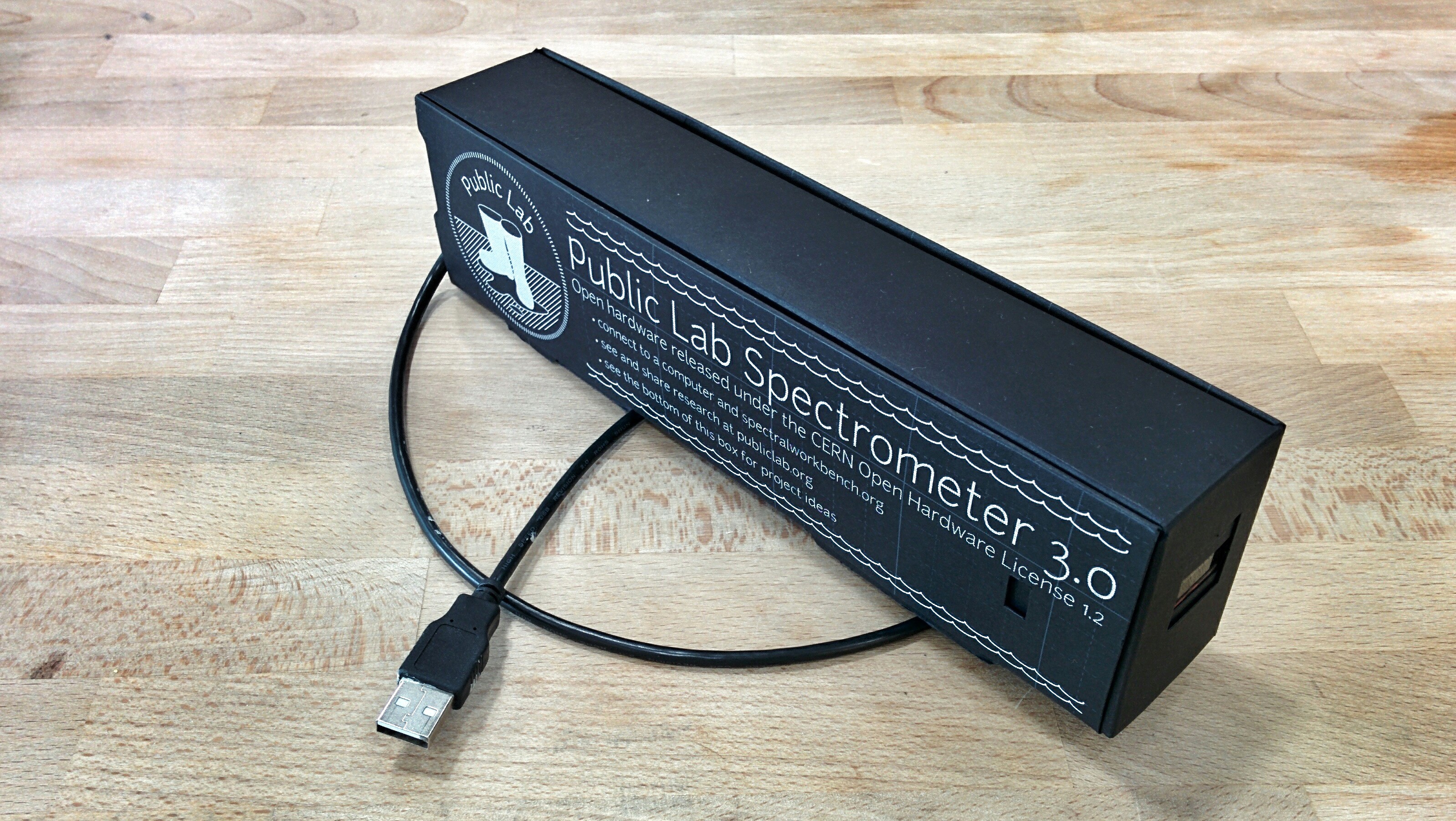
Parts List

- two-piece box
JDEPC-OV04 "gumstick" webcam with USB cable. (Datasheet: Spec_of_JDEPC-OV04_Ver_1.01.pdf) -- note, this is not the same "gumstick" webcam as used in the 2.5 Desktop Spectrometry Kit.
_Webcam is purchased in bulk from China. For more details E-mail kits@publiclab.org _
extra paper for modifications
- 45 degree wooden (ash) camera block, 3 cm x 4 x 4cm
wooden (ash) bench 1/4" (6mm) x 40mm x 235mm
_Wood products are sourced locally in Portland, OR at Roeder Woodworking _
one 65-degree fold up collimation angle
- one 45-degree fold-up camera angle.
- 50cm of 3/4" (2cm) width adhesive-backed loop fastener (Velcro-style)
25cm of 3/4" (2cm) width adhesive-backed hook fastener (Velcro-style)
_We buy our velcro from McMaster Carr in bulk here. The two part numbers are 9489K21 and 9489K201 _
one DVD-R
We buy ours from Amazon, choosing the cheapest option at time of purchase
photo emulsion printed slit 0.4mm wide printed on .004" acetate. (Design files on GitHub)
Acetate is something made custom for Public Lab by Camera Graphics
6 yard roll of 1/8" Thermoweb Supertape double sided tape. (3mm wide)
- printed assembly instructions (below)
Also see this longer illustrated parts list.
Assembly
Your spectrometer is composed of three functional elements:
- a collimation slit that works as a lens, only allowing parallel light rays through its apeture.
- a diffraction grating that deflects light more the lower the light's wavelength, creating a rainbow diffraction pattern.
- a camera to capture the diffraction pattern, focused on the collimation slit.

These elements are mounted on an adjustable velcro bench in a black paper box.

Bench
Put velcro on the bench
Everything is built up from the bench, an ash board 4cm (1.75 inches) wide. We will cover it with the loop tape (fuzzy side of the velcro).


The velcro loop tape is slightly wider than half the width of the bench, two strips will hang over each edge a bit.

Assemble the camera block
You will need the camera, double-sided tape, the block, and the hook side of the velcro tape. Try to hold the camera by its edges, as it can be sensitive to electrical shorts.

Start by putting a strip of double-sided tape on the back side of the camera:

Remove the pink protective film from the double-sided tape and attach to the center of the block's 45-degree angled side, with the white cable port on top:


On the underside of the block, attach two short strips of the hook tape (the Velcro's scratchy side).

OPTIONAL: Make the camera focus more precise. The camera's tiny lens is pre-focused to roughly 200mm at the factory, but you can do a little better. This requires twisting the lens until it is no longer held in place by the green glue on the lens, which is easiest after the camera is mounted on the block. Pliers may be needed. Once loose, point the camera at a target (like text) 200mm away and carefully twisting the camera lens until the image is in clearest focus.
See more research on lens focus.
Make a diffraction grating from a DVD
Do not touch the surface of the DVD, always hold it by the edges, fingerprints will blur this important optical component.
We are going to turn a DVD-R into a diffraction grating, a device for separating light by frequency. An ideal diffraction grating would create a straight rainbow. A DVD produces a curved rainbow, but its rigidity and consistency make it a very good grating, and the tiny webcam lens curves the spectrum anyways. Aligning your diffraction grating will take some tweaking. We’ve given you extra material to help.

We have three steps, cutting a quarter of the DVD out, peeling off the reflective aluminum side, and trimming to a small piece.

OPTIONAL: Wash the purple ink off of the DVD fragment for greater light transmission, as described in this note.
Peel apart a quarter of the DVD
Cut out a quarter of the DVD with scissors. It may take more than one try to get a good diffraction grating, so save the rest too.
Use a knife or a fingernail to dig under the corner of the DVD quarter and peel the two layers apart.


You will get two layers. We are trying to get a transparent purple piece without aluminum stuck to it. If you can’t find a good piece you may want to try another quarter DVD. You only need a 2cm (.75”) square cut from the outer edge. Trim down to a small square with roughly 2cm of the DVD’s outer edge.

Trim down to a small square with roughly 2cm of the DVD's outer edge.

Assemble the diffraction grating angle
You will need:

Overview:

When taping the three flaps together, make sure the bottom flaps are lined up. put hook tape on the bottom.


Put the outer edge of the dvd at the mid-point of the hole, and then remove the handles from the binder clip.

Put velcro on the bottom.

Put the outer edge of the DVD at the mid-point of the hole, and then remove the handles from the binder clip.

Assemble the slit card
You will need:

The collimation slit should be in the DVD sleeve.
_We will attach the slit using the tape as single sided tape-- tape it on top and DO NOT remove the backing film. _ Line up the collimation slit with the line on the slit card.
Assemble the box
Watch this step-by step video:
For the purposes of this instructional I've highlighted the edges of the box in white and used an unprinted box. Your box will have a printed and unprinted sides, and no white edges.
Place the box with the printing facing down. Pre-crease all the creases towards you. and crease the box top as well.


Fold the left side "T" shape over to the right, and insert the tab from the leftmost edge into the slot at the base of the "T", as shown here:

Lay the separate box top piece on top so that its tabs line up with the slots in the box bottom’s right side. Make sure the small rectangular holes on the top and bottom of the box line up. We will put the webcam cable through that hole later. Insert the tabs together. The box top will not lay flat-- don't worry. this is because there is extra space for the two sheets to fold together.


Now open the box back up and fold left and right side flaps to the middle to form the inner walls. They will hook together.


Fold the outer walls up and over the inner walls. Use the two circular holes in the outer walls to position the inner walls while folding the outer wall over.


Flip the box upside down and make sure the tabs have all popped out of the bottom of the box. Walk your fingers along the inside of the box and make sure all the tabs are popped out of the bottom.

Put it all on the bench

Line up the the bench with the side of the box, and align the camera's lens with the 200mm marker on the side of the box. Press the camera block down firmly.

Place the diffraction grating angle directly in front of the camera block and press it down firmly.

Slide the slit card in the front of the box. The printing is slightly off, unfortunately. level the slit card's line just above the box's line. the card should wedge in place on its bottom edge.


Push the camera cable through the cable hole in the back of the box:

You can add a knot in the cable to help stabilize it so that any pulling on the cable doesn't move the webcam:

Plug it into the camera-- it only fits one way, don't force it.

Slide the bench in at an angle, placing it down by the cable hole, and then pushing it down to the bottom.

Complete!
You're now ready to head to Spectralworkbench and calibrate your spectrometer
After you've done that, check out some of our other community submitted activities and if you have your own, submit it here!
5 Comments
@hagitkeysar awards a barnstar to abdul for their awesome contribution!
Reply to this comment...
Log in to comment
There's been lots of talk of skipping the Velcro steps, and directly gluing/taping the blocks to the board. @abdul posted a build that uses no wood and no velcro but removing velcro would increase rigidity while removing the wood would decrease it.
I wonder if we could explore a smaller change of just skipping the velcro, and perhaps another of knotting or otherwise trapping the cable to reduce the risk of tugging on the camera, which could throw off calibration.
Reply to this comment...
Log in to comment
Note: added section on rough treatment after the stress tests.
Reply to this comment...
Log in to comment
Hi, Abdul - could you link to the PDF design files for the box entry in the Materials list? https://github.com/publiclab/spectrometer3
Thanks!
Is this a question? Click here to post it to the Questions page.
Reply to this comment...
Log in to comment
Where can i get a PDF file to print those layout for the spectroscope ?
Is this a question? Click here to post it to the Questions page.
Reply to this comment...
Log in to comment
Login to comment.