I attended a Use Your Sensors event yesterday hosted by @charlotte_clarke and @rollinrenola where we used the DF Robot Turbidity sensors built like this prototype by @wmacfarl (https://publiclab.org/notes/wmacfarl/11-11-2019/building-the-simple-turbidity-sensor-prototype).
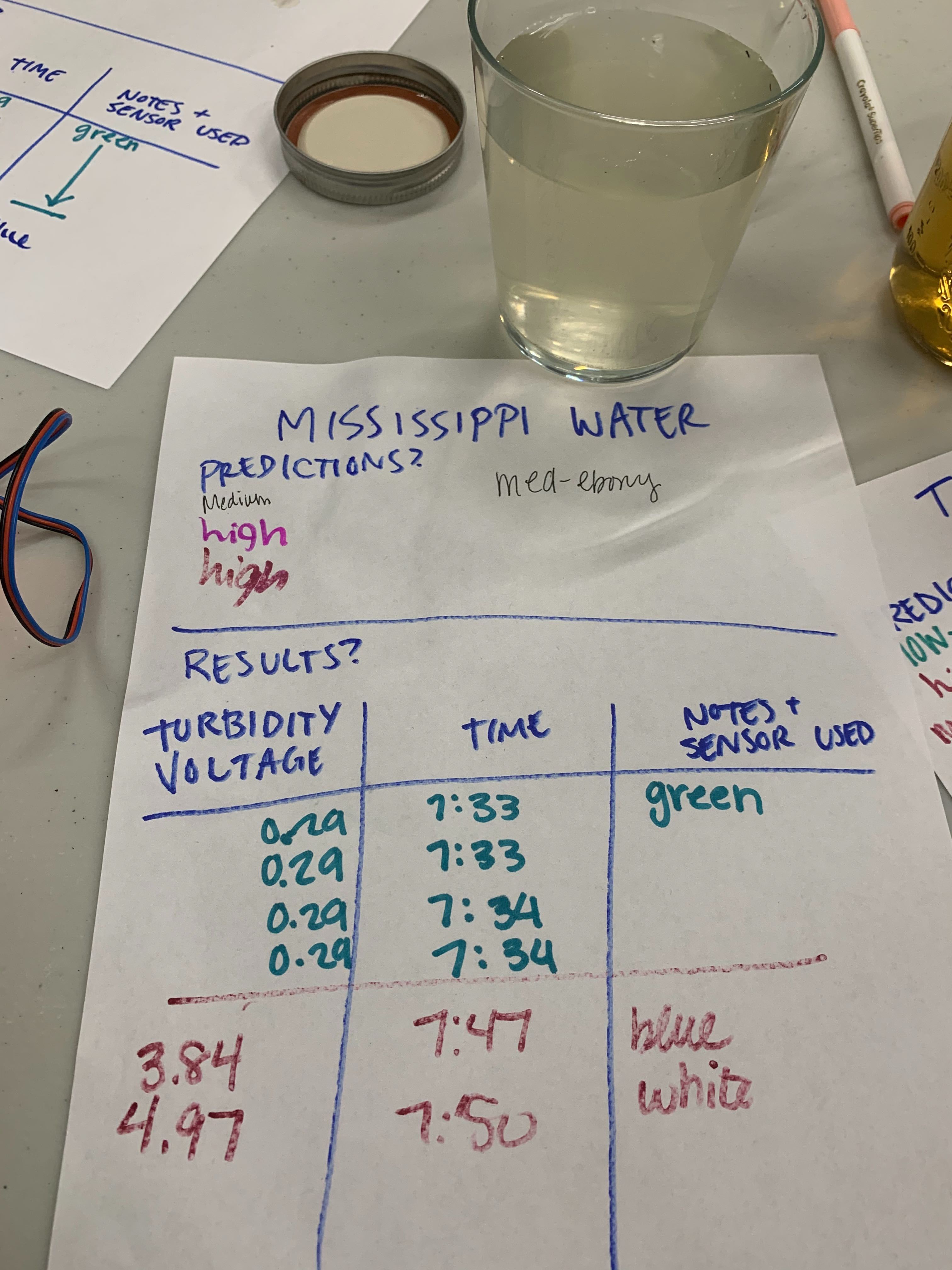
We noticed that the sensors were giving very different readings. One sensor would read the voltage of the water at 0.29 and another sensor would read that same sample at 3.94.
Here are some other observations:
- the sensors with low/high readings stayed low or high no matter the sample
- the LED's that blink corresponding to turbidity were blinking very quickly (even when off) on the low-reading sensors and very slowly on the high-reading sensors. See the gifs below
Blue-breadboard sensor (readings between 3.0 and 5.0) whose LED blinks slowly

Black-breadboard sensor (readings between 0.20 and 0.40) whose LED blinks quickly

Here are my major questions:
- what is a good way to test a sensor to know if it's working?
- where do we begin when troubleshooting?
- can I use the LED as a way to tell if my sensor is working properly?
- how can I fix the sensor and which one is broken?
Please add any other things you can remember @charlotte_clark and @rollinrenola!
Reply to this comment...
Log in to comment
@mimiss These sensors are cheap because they have limited accuracy, they were designed for dish-washers and the like, not technical analysis. However, I am using them on a project (capturing data to a Raspberry Pi) and they give some good 'ballpark' readings. The best way is to calibrate them against a good turbidity meter. I would suggest making up some control samples and see if you can find an environmental group with a turbidity meter that can measure them for you. Then use them to calibrate the DB Frost sensors. I am with a group that has a turbidity meter, so we did some parallel testing of samples with all the meters for comparison.
Reply to this comment...
Log in to comment
Hey, I have a couple of questions that may help to look at the hardware side:
Did you use a phone cable for the USB or is it a legit cable used for microcontrollers (have run into problems pretty frequently if it's a phone cable)
The wires that join to the switch--are they soldered or just wrapped around? They would definitely need to be soldered for a good connection.
The blue/red/black wires that you have that join--are the red and black in the correct position so they match the ones you are joining? (Yeah, obvious but worth a check :))
Did you solder the header onto the Arduino (the pins that go into the breadboard) or did it come pre-soldered?
That's it for now. It may be good to post pics of your boards/connections--kind of hard to tell by the gifs. All in all things look good from what you have posted. :)
Is this a question? Click here to post it to the Questions page.
Reply to this comment...
Log in to comment
I think there is a little screw that can be turned to "tune" each sensor board, so I wonder if you could put both in the same sample and use a small screwdriver to adjust them to match?
This is a great thread!
Is this a question? Click here to post it to the Questions page.
This screw actually /doesn't/ calibrate the sensor. It sets the /threshold/ for digital output.
I completely forgot about this when I wrote my research notes and I should fix it!
The sensor board has a switch on it that you can switch between D(igital) and A(nalog.)
If the sensor board is set to Digital it will send a HIGH signal (approximately 4.5V to 5V) when the "turbidity" is above a certain threshold and a LOW (approximately .2V to .5V). You set that threshold by turning that screw.
If the sensor board is set to Analog, it will send a signal ranging from 0V to 5V.
My /guess/ is that one of your sensors was set to "Digital" -- the one that was giving you a .2V to .4V reading.
I did some testing of individual sensors that I had lying around and they all gave roughly consistent readings (varying by .1 to .2) so there was not a lot of variablity among the three sensors I have. I will write up some more of this testing data in a separate note.
Is this a question? Click here to post it to the Questions page.
Reply to this comment...
Log in to comment